Sony tc vf 1 service manual

This is the 35 pages manual for sony tc vf 1 service manual.
Read or download the pdf for free. If you want to contribute, please upload pdfs to audioservicemanuals.wetransfer.com.

Page: 1 / 35
sony tc vf 1 service manual

Extracted text from sony tc vf 1 service manual (Ocr-read)


Page 1

TC-VFI

SERVICE MANUAL AEP Model

E Model

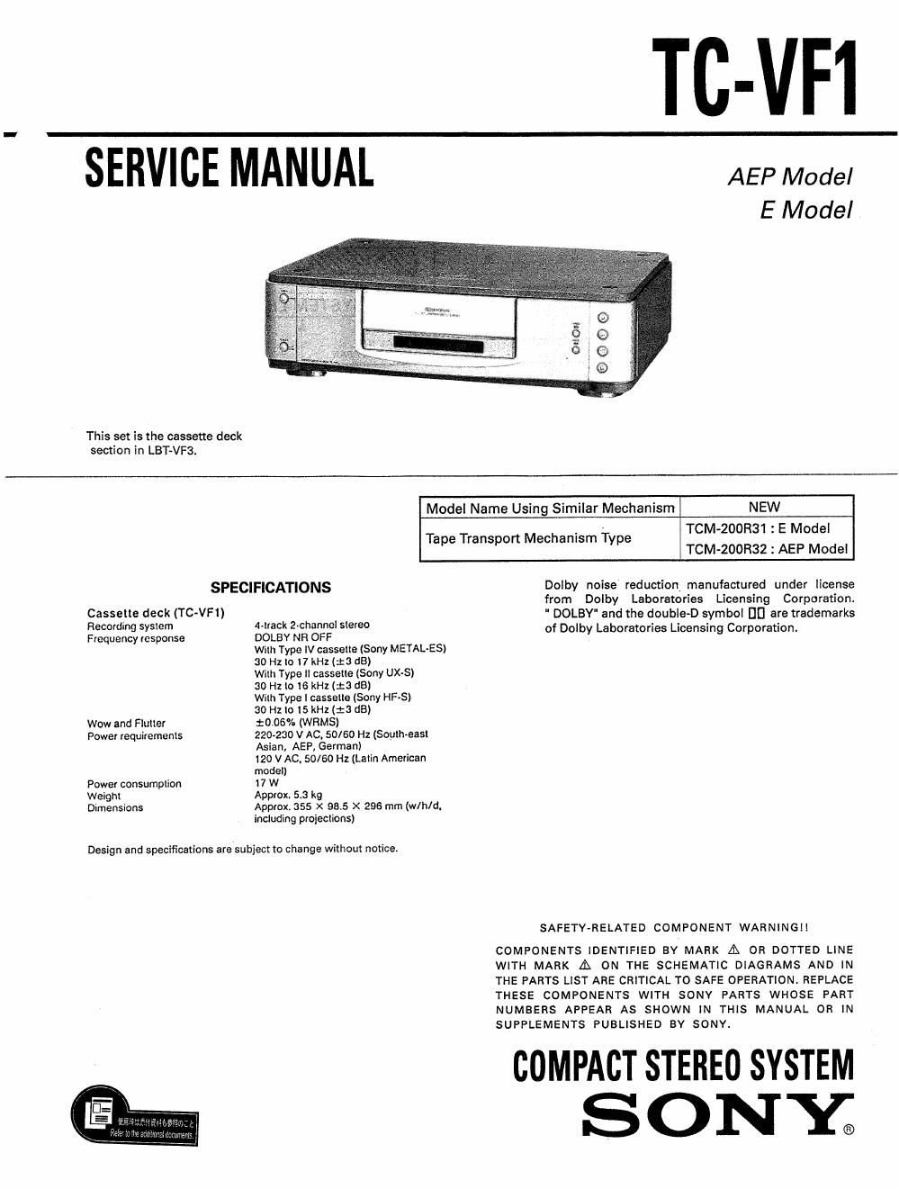
This set is the cassette deck
section in LBT~VF3.

Model Name Using Similar Mechanism NEW
TCM-200R31 : E Model
TCMv200R32 : AEP Model

Tape Transport Mechanism Type

SPECIFICATIONS Dolby noise reduction manufactured under license
from Dolby Laboratories Licensing Corporation.
gasszlle deck (TCVF) 4 k 2 h 1 I " DOLBY" and the double-D symbol [II] are trademarks
860' mg System V tac -0 anne S 8180 . . .
quuencymsponse DOLBY NR OFF of Dolby Laboratories Licensmg Corporation.

Willi Type IV cassette (Sony METAL-ES)
80 Hz lo 7 kHz (13 dB)
With Type ll cassette (Sony UX-S)
30 H2 lo 16 kHz (:3 d8)
thh Type 1 casselie (Sony HF-S)
30 Hz lo l5kHz (:3 (13)
Wow and Fluuet 10.06% (WRMS)
Power requiremenls 220-230 V AC. 50/60 Hz (Soyihveast
Asian, AEP, German)
120 v AC, 50/60 Hz (Latin American

model)
Power consumption I 7 W
Weight Approx. 5.3 kg
Dimensions Approx. 355 X 98.5 X 296 mm (w/h/d.

including proiections)

Design and specifications sresubiect to change without notice.

SAFETY-RELATED COMPONENT WARNING

COMPONENTS IDENTIFIED BY MARK A OR DOTTED LINE
WITH MARK A ON THE SCHEMATIC DIAGRAMS AND IN
THE PARTS LIST ARE CRITICAL TO SAFE OPERATION. REPLACE
THESE COMPONENTS WITH SONY PARTS WHOSE PART
NUMBERS APPEAR AS SHOWN IN THIS MANUAL OR IN
SUPPLEMENTS PUBLISHED BY SONY.

COMPACT STEREO SYSTEM
S O N Y;

Page 2

TC-VFI

TABLE OF CONTENTS MODEL IDENTIFICATION
- SPECIFICATION LABEL -

seam m Pig:
1' SERVICE NOTE SONYQ MODEL Not TC-VFi

1-1. Ejecting Disabled (Motor Disabled) ................ 3 STEREO CASSETTE DECK

1-2. Cassette Holder not Returned

(Motor Disabled) .. 3

2. GENERAL ................. 4
3. ADJUSTMENTS I:I SYSTEM LBT'VFl

31. Mechanical Adjustment .................................. 6 seam N0, T

3-2. Electrical Adjustment ...................................... 6 MADE 'N JAPAN

Germany Model

4. DIAGRAMS I I
4-1. Circuit Boards Location .................................. 11
4-2. Block Diagram ........................
4-3. Semiconductor Lead Layouts.

4-4. Printed Wiring Boards
(Display/Power Supply Section) ..................... 16

4-5. Schematic Diagram
(Display/Power Supply Section) ................. 19

46. Printed Wiring Boards (Audio Section) ..... 22
4-7. Schematic Diagram (Audio Section) .............. 25

4-8. Schematic Diagram
(System Control Section)

4-9. Printed Wiring Boards
(System Control Section) ............................... 33

5. EXPLODED VIEWS

AEP, Germany Model : AC 220 » 230V, 50/60H2
E; 120V Model : AC120V ~ 50/60Hz 17W
E; 220 - 230V Model : AC220 - 230V ~ 50/60HZ 17W

......... 29

5-1. Cabinet Section ..... 36
5-2. Chassis Section... ..... 37
5-3. Mechanism Section 1 .. ..... 38
5-4 Mechanism Section 2.. ..... 39
5-5. Mechanism Section 3 ..................................... 40
6. ELECTRICAL PARTS LIST ............................ 41