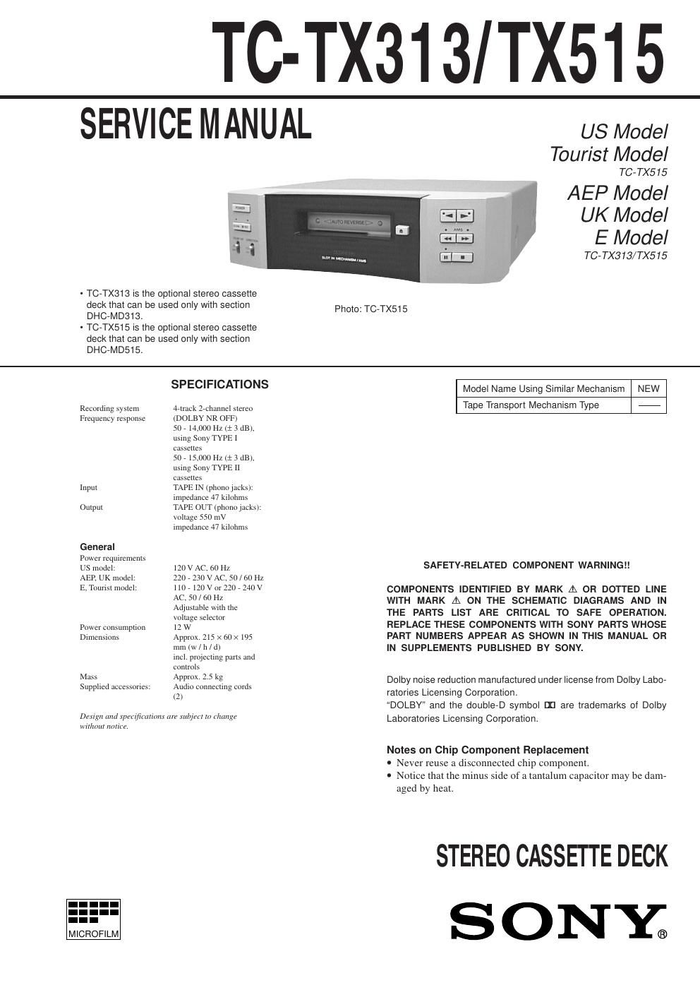
Sony tc tx 515 service manual
This is the 34 pages manual for sony tc tx 515 service manual.
Read or download the pdf for free. If you want to contribute, please upload pdfs to audioservicemanuals.wetransfer.com.
Extracted text from sony tc tx 515 service manual (Ocr-read)
Page 1
Ð 2 Ð TABLE OF CONTENTS 1. GENERAL Parts and Controls ...................................................................... 3 2. TEST MODE 2-1. Checking the Items of Test Mode ......................................... 4 3. DISASSEMBLY 3-1. Top Cover .............................................................................. 5 3-2. Front Panel Assy ................................................................... 5 3-3. Front Board (TC-TX313) ...................................................... 6 3-4. Panel Board (TC-TX515) ...................................................... 6 3-5. Back Plate ............................................................................. 7 3-6. Bracket (Power Trans) .......................................................... 7 3-7. Main Board ........................................................................... 8 3-8. TCM Assy ............................................................................. 8 3-9. Lever ..................................................................................... 9 3-10. Tension Spring ....................................................................... 9 3-11. Housing ............................................................................... 10 3-12. Chassis ................................................................................ 10 3-13. Motor (A)/(B) Assy .............................................................. 11 3-14. Head Plate ............................................................................ 11 3-15. Pinch Roller Assy ................................................................ 12 3-16. Bracket (Head Unit) ............................................................ 12 4. MECHANICAL ADJUSTMENTS ................................. 13 5. ELECTRICAL ADJUSTMENTS ................................... 13 6. DIAGRAMS 6-1. Circuit Boards Location ...................................................... 16 6-2. Printed Wiring Board ÐDeck SectionÐ ................................ 17 6-3. Schematic Diagram ÐDeck SectionÐ ................................... 18 6-4. Printed Wiring Boards ÐMain SectionÐ .............................. 20 6-5. Schematic Diagram ÐMain SectionÐ ................................... 23 6-6. Printed Wiring Boards ÐFront Panel SectionÐ .................... 27 6-7. Schematic Diagram ÐFront Panel SectionÐ ......................... 29 6-8. IC Pin Description ............................................................... 31 7. EXPLODED VIEWS 7-1. Top Cover Section ............................................................... 33 7-2. Front Panel Section (TC-TX313) ........................................ 34 7-3. Front Panel Section (TC-TX515) ........................................ 35 7-4. Chassis Section ................................................................... 36 7-5. TCM Assy Section .............................................................. 37 8. ELECTRICAL PARTS LIST ........................................... 38
Page 2
Ð 3 Ð SECTION 1 GENERAL ¥ TC-TX313 Parts and Controls ¥ TC-TX515 Parts and Controls 1POWER switch Only the power to this set is turn on. 2Cassette slot With a cassette inserted, the cassette indicator is illuminated red when the power is turned on. 3¤ (eject) button 4» (lower side play)/ á (upper side play) button Even without cassette, the power to this set and the DHC-MD313 will be turned on when one of these buttons is pressed. 5Õ (pause) button 6p (stop) button 7¼/â (fast forward, fast backward/AMS) button 8¨ REC (recording) button 9CD SYNC (CD synchro) button This button allows CD synchro recording to be executed as this set is interlocked with the DHC-MD313. !¼DIRECTION switch !ÁDOLBY NR (Dolby Noise Reduction) switch1POWER switch Only the power to this set is turn on. 2Cassette slot With a cassette inserted, the cassette indicator is illuminated red when the power is turned on. 36 (eject) button 49 (lower side play)/ ( (upper side play) button 5p (stop) button 6P (pause) button 70/) (fast forward, fast backward/AMS) button 8r REC (recording) button 9DIRECTION switch !¼DOLBY NR (Dolby Noise Reduction) switch !ÁCD SYNC (CD synchro) button This button allows CD synchro recording to be executed as this set is interlocked with the DHC-MD515.