Sony tc rx 410 service manual

This is the 21 pages manual for sony tc rx 410 service manual.
Read or download the pdf for free. If you want to contribute, please upload pdfs to audioservicemanuals.wetransfer.com.

Page: 1 / 21
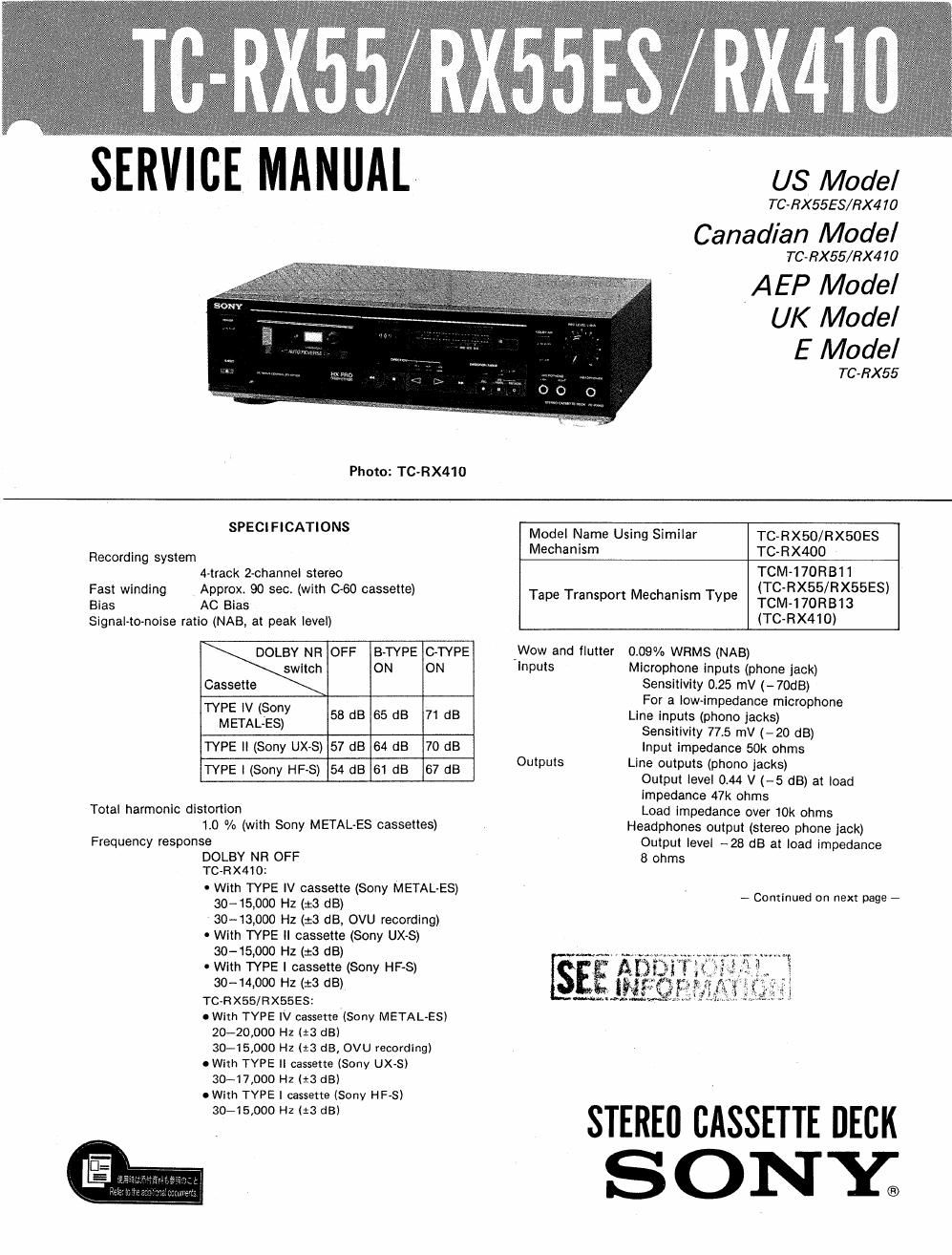
sony tc rx 410 service manual

Extracted text from sony tc rx 410 service manual (Ocr-read)


Page 2

TC-RX55/RX55ES/RX41 0

General
Power requirements
US,Canadian, E2 model: 120 V AC, 60 Hz
AEP, E3 model: 220 V AC, 50/60 Hz
UK model: 240 V AC, 50/60 Hz
Power consumption
22 W (TC-RX410l
19 W (Tonxss/Rxsaesl
TC-RX410:
Approx. 430 x 118 x 295 mm (w/h/d)
(17 x 43/: X11S/s inches)
TC-RX55/RX55ES:
Approx. 430 x 120 x 285 mm (w/h/dl
(17 x 43/. x11/4 inches)
including projecting parts and controls
Approx. 3.9 kg (8 lbs 10 oz)

Dimensions

Weight
Supplied accessory
Connecting cord (2)

Design and specifications are subject to change without notice.

MODEL IDENTIFICATION (TC-RX55)
- Specification Label Printed on Back Panel -

SONYa MODEL N0.TC-RX55

STEREO CASSETTE DECK

o The Dolby HX PRO* system to improve the linearity

of the tapes high~range response during recording.

0 Cue & review and memory play functions to provide

easy access to a desired position.

0 B and C type Dolby NR* systems to reduce tape hiss

noise.
0 The optional remote control unit allows various
operations to be remotely controlled.

* Dolby noise reduction and HX Pro headroom extension
manufactured under license from Dolby Laboratories

Licensing Corporation HX Pro originated by Bang & Olufsen.

"DOLBY", the double-D symbol DD and HX PRO" are
trademarks of Dolby Laboratories Licensing Corporation

SAFETV-RELATED COMPONENT WARNING

COMPONENTS IDENTIFIED BY MARK A OR DOTTED
LINE WITH MARK A ON THE SCHEMATIC DIAGRAMS
AND IN THE PARTS LIST ARE CRITICAL TO SAFE
OPERATION. REPLACE THESE COMPONENTS WITH
SONY PARTS WHOSE PART NUMBERS APPEAR AS
SHOWN IN THIS MANUAL OR IN SUPPLEMENTS PUB-
LISHED BY SONY.

ATTENTION AUCOMPQSANT AYANT RAPPORT
A LA SECURITE!

LES comrosmrs IDENTIFIES PAR UNE MAROUE A
sun LES DIAGRAMMES SCHEMATIOUES ET LA LISTE
DES PIECES sour cmriouEs POUR LA sécuniré
DE FONCTIONNEMENT. NE REMPLACER css com.
POSANTS QUE PAR DES PIECES sonv DONT LES
numénos sour oomnés DANS cs MANUEL ou
DANS LES SUPPLEMENTS PUBLIES PAR soNV.

\\Cl

SERIAL NO.
MADE IN JAPAN

AEP, E3 Model: AC 220 V ~ 50/60 Hz
UK Model: AC 240 V ~ 50/60 Hz
Canadian, E2 Model: AC 120 V 60 Hz 19 W

-@@® © ® : AE20nly

TABLE OF CONTENTS

Section Title Page
Specifications ....................... 1
Features ........................... 2
Model Identification ................... 2
Safety Check-out .................. 3
1. G ENERAL

Identification of Front Panel Parts ...... 3
2. ADJUSTMENTS
2-1. Mechanical Adjustments ............ 4
22. Electrical Adjustments .............. 4
34 DIAGRAMS
3-1. Printed Wiring Boards .............. 8
3-2. Schematic Diagram ................ 1 l
4. EXPLODED VIEWS ............... 15
5. ELECTRICAL PARTS LIST ......... l9