Sony tc k 690 es service manual
This is the 47 pages manual for sony tc k 690 es service manual.
Read or download the pdf for free. If you want to contribute, please upload pdfs to audioservicemanuals.wetransfer.com.
Extracted text from sony tc k 690 es service manual (Ocr-read)
Page 1
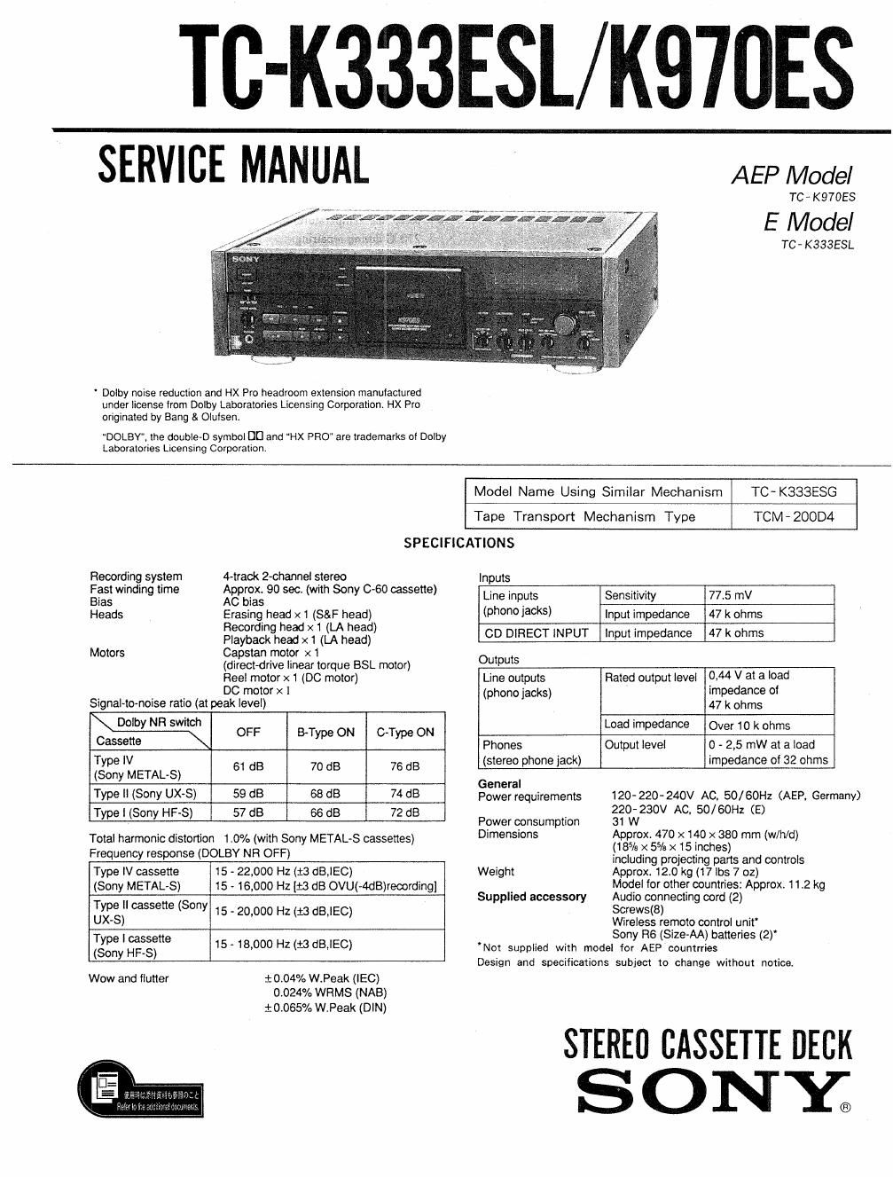
TC-K333ESL/K970ES
SERVICE MANUAL
AEP Model
TC , K 97053
TC- K333ESL
' Dolby noise reduction and HX Pro headroom extension manulactured
under license lrom Dolby Laboratories Licensing Corporation. HX Pro
originated by Bang 8. Olutsen.
DOLBY, the double-D symbol DI] and "HX PRO are trademarks or Dolby
Laooratories Licenslng Corporation,
Model Name Using Similar Mechanism TC- K333ESG
Tape Transport Mechanism Type TCM - 200D4
Recording system
Fast winding time
Bias
Heads
Motors
SPECIFICATIONS
4-traok 2»channel stereo
Approx. 90 sec. (with Sony 060 cassette)
AC bias
Erasing head X 1 (S&F head)
Recording head x 1 (LA head)
Playback head x 1 (LA head)
Capstan motor x 1
(directorive linear torque BSL motor)
Reel motor x 1 (DC motor)
DC motor x 1
Signal-to-noise ratio (at peak level)
Dolby NR switch
Cas-sate- OFF BType ON C-Type ON
25:32:,13 AL 8) 61 dB 70 dB 76 dB
Type II (Sony UX-S) 59 dB 68 dB 74 dB
Type I (Sony HF-S) 57 dB 66 dB 72 dB
Total harmonic distortion 1.0% (with Sony METAL-S cassettes)
Frequency response (DOLBY NR OFF)
Type IV cassette
(Sony METALS)
15 - 22,000 Hz (:3 dB,IEC)
15 - 16,000 HZ {1'3 dB OVU(-4dB)reoording]
Type II cassette (Sony
UX-S)
15 - 20,000 Hz (13 dB,IEC)
Type I cassette
(Sony HF-S)
15 - 18,000 Hz (:3 dBJEC)
Wow and flutter
mom W.Peak ("50)
0402479 WRMS (NAB)
mossy, W.Peak (DIN)
Inputs
Line inputs Sensitivity 77.5 mV
(phono jacks) Input impedance 47 k ohms
CD DIRECT INPUT Input impedance 47 k ohms
Outputs
Line outputs
(phono jacks)
0.44 V at a load
impedance of
47 k ohms
Rated output level
Load impedance Over 10 k ohms
Phones
(stereo phone jack)
0 - 2,5 mW at a load
impedance of 32 ohms
Output level
General
Power requirements
Power consumption
Dimensions
Weight
Supplied accessory
120- 220- 240V AC. 50/ 60H: (AEP. Germany)
220- 230V AC, 50/ GOHz (E)
31 W
Approx 470 x 140 x 380 mm (w/h/d)
(18% X 55/3 x 15 inches)
including projecting pans and controls
Approx. 120 kg (17 lbs 7 02)
Model for other countries: Approx. 112 kg
Audio connecting cord (2)
Screws(8)
Wireless remote control unit
Sony R6 (Size-AA) batteries (2)'
Not supplied with model for AEP countrries
Design and specifications subject to change without notice
STEREO CASSETTE DECK
SONY;
Page 2
TC- K333ESL/ K97OES
TABLE OF CONTENTS
m m 1282
SPECIFICATIONS ..................................... 1
MODEL IDENTIFICATION ~~~~~~~~~~~~~~~~~~~~~~~~~~~ 3
I. GENERAL ......................................... 4
2 DISASSEMBLY ................................... 8
3. APJUSTMENTS
3- l. Mechanical Adjustments ~~~~~~~~~~~~~~~~~~~~~~ 10
3- 2. Electrical Adjustments ~~~~~~~~~~~~~~~~~~~~~~~~ 12
4. DIAGRAMS
4-1-1. ICSOZ, 505 (CX20188) Pin Functions """"" 17
4-1-2. IC601 (M50940-3135P) Pin Functions ~~~~~~ 18
4-1-3. IC801 (M5096472205P) Pin Functions ~~~~~~ 19
47141. IC881 (HD404240A8OS) Pin Functions ~~~~~ 20
4-2. Circuit Boards Location ~ . 20
4A3. IC Block Diagrams ............................. 21
474. Semiconductor Lead Layouts ----------------- 22
4-5 Block Diagram ................................. 23
4-6. Printed Wiring Boards
_ Audio Section _ ............................ 27
4-7. Schematic Diagram
_ Audio Section _ ............................ 31
4'8. Schematic Diagram
_ Syscon Section _ ........................... 35
4- 9. Printed Wiring Boards
_ Syscon Section _ ........................... 39
5t EXPLODED VIEWS
571. Overall Section ------------------------------ 48
5-2. Front Panel Section ~- ~ 44
5-3. Chassis Section ................................ 45
5~4. Mechanism Section-1
(TCM_2()0D4) ................................. 45
5-5. Mechanism Section-2
(TCM- 200134) ................................. 47
6. ELECTRICAL PARTS LIST ----------------------- 48
Notes on chip component replacement
0 Never reuse a disconnected chip component.
0 Notice that the minus side of a tantalum capacitor may
be damaged by heat
Flexible Circuit Board Repairing
0 Keep the temperature of the soldering iron around
270°C during repairing.
0 Do not touch the soldering iron on the same conductor
of the circuit board (within 3 times).
0 Be careful not to apply force on the conductor when
soldering or unsoldering.
Tc-K333ESL: E Model
Operating Voltage
Before connecting the unit to the power source, check that
the operational voltage of your unit is the same as the local
power supply.
Where purchased Operating voltage
European countries 220 - 230 V AC, 50/60 Hz
120, 20 or 240 V AC adjustable. 50/60
Hz
A voltage selector is located on the rear
panel. If the selector must be reset,
disconnect the Ac power cord and set
the selector to the appropriate voltage
Other countries
VOLTAGE VOLTAGE selector
SAFETY-RELATED COMPONENT WARNINGII
COMPONENTS IDENTIFIED BY MARK A 0R DOTTED
LINE WITH MARK A ON THE SCHEMATIC DIAGRAMS
AND IN THE PARTS LIST ARE CRITICAL TO SAFE
OPERATION. REPLACE THESE COMPONENTS WITH
SONY PARTS WHOSE PART NUMBERS APPEAR AS
SHOWN IN THIS MANUAL OR IN SUPPLEMENTS PUB-
LISHED BV SONY.