Sony tc h 3600 service manual

This is the 38 pages manual for sony tc h 3600 service manual.
Read or download the pdf for free. If you want to contribute, please upload pdfs to audioservicemanuals.wetransfer.com.

Page: 1 / 38
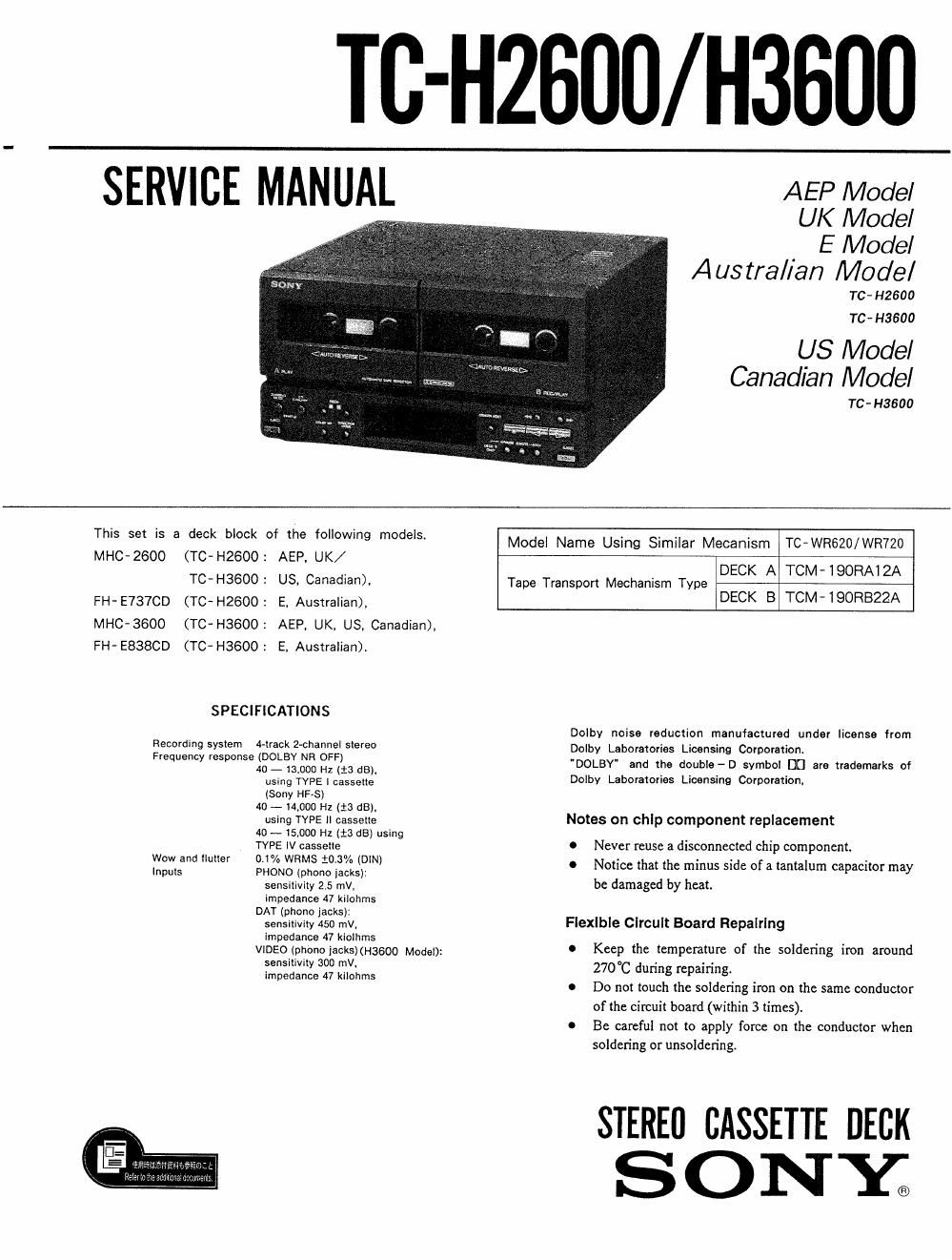
sony tc h 3600 service manual

Extracted text from sony tc h 3600 service manual (Ocr-read)


Page 1

TC-HZBOO/ H3600

SERVICE MANUAL AEP Model

UK Model
. E Model
Austral/an Model

TC- H2600
TC . H3600

US Model
Canadian Model

TC - H3600

5 59 5 3 d9 b'°°k °f "9 °"°Wi9 m°de's~ Model Name Using Similar Mecanism TC-WR620/WR720

MH - T -H2 : AEP. UK

C 260° ( c 600 / DECK A TCM-IQORAIZA
TC-H3600: US, Canadian), Tape Transport Mechanism Type

FH-E737CD (romeo: E, Australian), DECK B TCM'IQORBZZA

MHC-3600 (TC- H3600: AEP. UK. US, Canadian),
FH-E838CD (TC- H3600: E, Australian)

SPECIFICATIONS

Dolby noise reduction manufactured under license from

Recording syslem 4-lr30k 2-Channfil 9'90 Dolby Laboratories Licensing Corporation.
Frequency 'espmegcfl: SI; 3:? dB) 'DOLBY and the double - D symbol DC are trademarks of
using I'VPE | ca'sssfie' Dolby Laboratories Licensing Corporation,
(Sony HF-S)
4o - mooo Hz (:3 as).
using TYPE II casseue Notes on chip component replacement
40 ~ 15,000 Hz (i3 (13) using , ,
TYPE IV casseile 0 Never reuse a dlsconnected chlp component.
WOW and 1 °-% WRMS 13% (DIN) o otice that t us side ofa tanta m ca acito
Inputs PHONO (phone lacks): N he mm m p 1' may

sensltivity 25 mV, be damaged by heat.
impedance 47 kilohms
DAT (phone lacks):

sensntivlly 450 mv, Flexible circuit Board Repalrlng
impedance 47 kiolhms . .
VlDEO(phonoiacks)(Haeoo ModeI): 0 Keep the temperature of the soldering iron around

sensilivity 300 mV,

270° dun re ain'n.
impedance 47 kilohms c g P g

0 Do not touch the soldering iron on the same conductor
of the circuit board (within 3 times).

0 Be careful not to apply force on the conductor when
soldering or unsoldering.

STEREfl CASSETTE DECK
S 0 NY;

Page 2

TC- H2600/ H3600

TABLE OF CONTENTS

Section Title Page
1. GENERAL ......................................... 3
2. MECHANICAL ADJUSTMENTS ~~~~~~~~~~~~~~~~~~~ 4
3. ELECTRICAL ADJUSTMENTS ---------------------- 4
4. DIAGRAMS
4-1. IC Pin Description -------------------------- g
442. Block Diagram ............................. 12
4~3. Printed Wiring Boards ~Main Section-m 15
4-4. Schematic Diagram -Main Section- ------ 19

4- 5. Schematic Diagram

_Pin Jack Section_ ........................ 24
4-6. Printed Wiring Boards
-Pin Jack Section- ~~~~~~~~~~~~~~~~~~~~~ 29
477i Semiconductor Lead Layouts . 32
4-8. Circuit Boards Location 32
5. EXPLODED VIEWS
5-1. Front Panel Section-1-~~ - 83
5-2. Front Panel Section-2 34
5-3. Mechanism sectional ~~~~~~~~ . 35
5-4. Mechanism section>Z ~~~~~~~~~~~~~~~~~~~~~~ 36
6 ELECTRICAL PARTS LIST ~~~~~~~~~~~~~~~~~~~~~ 37

Caution when repairing

Normally the power of this set is supplied from the
lA-HZ600/H3600 amplifier connected. When only this
set is repaired, connect the power of 18V AC as shown
in the figure below.

AC18V

CNJ40|

SYSTEM CONTROL 2

I
].

MODEL IDENTIFICATION
-Specification Label--

TC- H2600
TC- H3600

SONY': MODEL NO.

STEREO CASSETTE DECK
SYSTEM

SERIAL NO.
MADE IN JAPAN

MHC- 2600 (TC- H2600 : AEP. UK/

TC- H3600 : US. Canadian).
FH' E737CD (TC- H2600 : E, Australian),
MHC-3600 (TCVH3600 : AEP, UK. US, Canadian).
FH- E838CD (TC- H3600 : E, Australian).

SAFETY-RELATED COMPONENT WARNING

COMPONENTS IDENTIFIED BY MARK A 0R DOTTED
LINE WITH MARK A ON THE SCHEMATIC DIAGRAMS
AND IN THE PARTS LIST ARE CRITICAL TO SAFE
OPERATION. REPLACE THESE COMPONENTS WITH
SONY PARTS WHOSE PART NUMBERS APPEAR AS
SHOWN IN THIS MANUAL OR IN SUPPLEMENTS PUB-
LISHED BY SONY.

ATTENTION AU COMPOSANT AYANT RAPPORT
A LA SECURITE!

LES cowosmrs IDENTIFIES PAR UNE MAROUE A
sun LES DIAGRAMMES SCHEMATIOUES ET LA LISTE
DES PIECES som camouEs POUR LA sécumré
DE FONCTIONNEMENT. NE REMPLACER css com.
POSANTS ous PAR DES PIECES sonv DONT LES
NUMEROS SONT DONNES DANS CE MANUEL ou
DANS LES SUPPLEMENTS PUBLIES PAR souv.

[PIN JACK BOARD) (conductor side)