Sony tc ex 5 service manual

This is the 24 pages manual for sony tc ex 5 service manual.
Read or download the pdf for free. If you want to contribute, please upload pdfs to audioservicemanuals.wetransfer.com.

Page: 1 / 24
sony tc ex 5 service manual

Extracted text from sony tc ex 5 service manual (Ocr-read)


Page 1

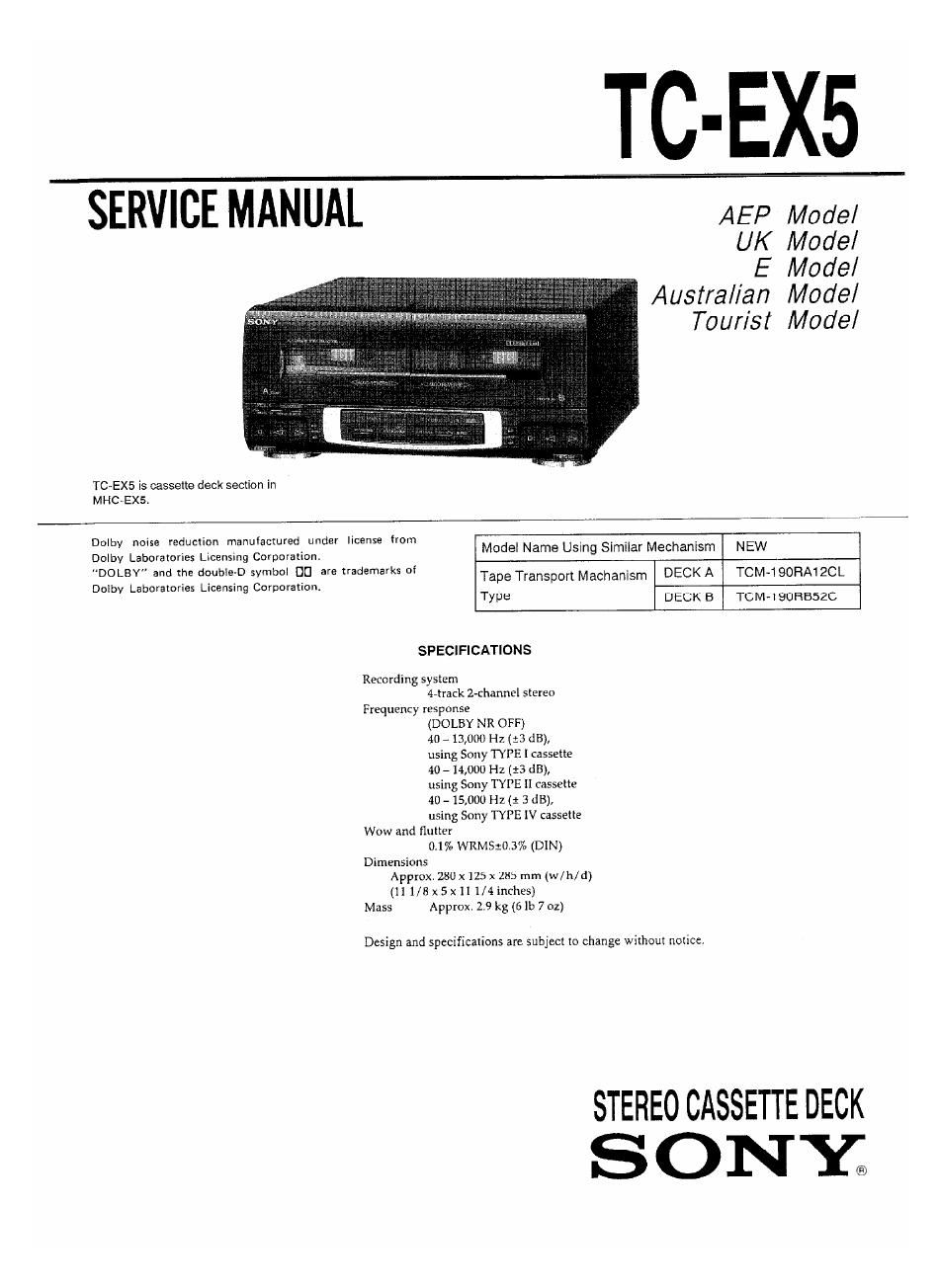
TC-EX5

SERVICE MANUAL AEP Model

UK Model

E Model
Austral/an Model
Tour/sf Model

TC~EX5 is cassette deck section in
MHCVEXS.

Dolby noise reduction manulactured under license from

Dolby Laboratories Licensing Corporation. Modal Name Usmg SImIIar Mechanism NEW

DOLBY" and true double-D symbol [IE] are Xrademarks Df Tape Transport Mechanism DECK A TCM-I 90RA1 ZCL
Dolby Laboratories Licensing Corporation. _
Type DECK B TCM-IQORBSZC
SPECIFICATIONS

Recording system
4-track 2-channel stereo
Frequency response
(DOLBY NR OFF)
40 e 13,000 Hz (:3 dB),
using Sony TYPE I cassette
40 -14,000 Hz (:3 dB),
using Sony TYPE II cassette
4o - 15,000 Hz (1 3 dB),
using Sony TYPE IV cassette
Wow and flulter
0.1% WRMS:().3% (DIN)
Dimensions
Approx. 280 x125 x 285 mm (w/h/d)
(11 1/8x5x1I1/4inches)
Mass Approx. 2.9 kg (6 lb 7 oz)

Design and specifications are subject to change without notice.

STEREO CASSETTE DECK
SONY;

Page 2

TABLE OF CONTENTS
Section Title Pflgn
. GENERALM
. ADJUSTMENTS

271. Mechanical Adjustments
2-2i Electrical Adjustments --

. EXPLANATION OF IC TERMINALS

. DIAGRAMS
4-1. Block Diagram --------
472. Printed Wiring Boards
4.3, Schematic Diagram ....................................

. EXPLODED VIEWS
5]. Chasm Section ............................................... 23
572 Front Panel Section -
5~3. Mechanism Section-


SAFETY-RELATED COMPONENT WARNING

COMPONENTS IDENTIFIED BY MARK A 0R DOTTED
LINE WITH MARK A ON THE SCHEMATIC DIAGRAMS
AND IN THE PARTS LIST ARE CRITICAL TO SAFE
OPERATION. REPLACE THESE COMPONENTS WITH
SONY PARTS WHOSE PART NUMBERS APPEAR AS
SHOWN IN THIS MANUAL OR IN SUPPLEMENTS PUB-
LISHED BY SONY.

SERVICING NOTE
- POWER SUPPLIED WHILE SERVICING

This unit does not work independently because of not having

the power supply.
It must be unite together with the ether units when repaired

5-4, Mechanism Section-2 ----------------------------------- Z6
. ELECTRICAL PARTS LIST ------------------------------- 27
SECTION 1
GENERAL , _ _
This Ramon Is extracted from
LOCATION OF CONTROLS Instruction manual.

Fl DOLBY NR selector (I5)

IE DIRECTION MODE selector (14)

I; Cassette compartments (14)

[Al Tape operating buttons (for deck A)
t> (front side play) (14)
<1 (reverse side play) (14)
[I (stop) (14)
» (last rightward and AMS") (14)
« (fast leftward and AMS") (14)
A EJECT butt0n(14)

El CD SYNCHRO button (15)

LE] DUBBING MODE butIon (19)

m Display window

IE Tape operaling buttons (for deck B)

I> (front side play) (14)

<1 (reverse side play) (14)

I] (stop) (14)

» (fast rightward and AMS") (14)
« (fast leftward and AMS") (14)
ll PAUSE (14)

O REC MUTE button (16)

O REC (recording) (16)

: EJECT bulIon (14)

AMS: Aulumatic Music Sensor(14)