Sony ta ve 215 service manual

This is the 30 pages manual for sony ta ve 215 service manual.
Read or download the pdf for free. If you want to contribute, please upload pdfs to audioservicemanuals.wetransfer.com.

Page: 1 / 30
sony ta ve 215 service manual

Extracted text from sony ta ve 215 service manual (Ocr-read)


Page 1

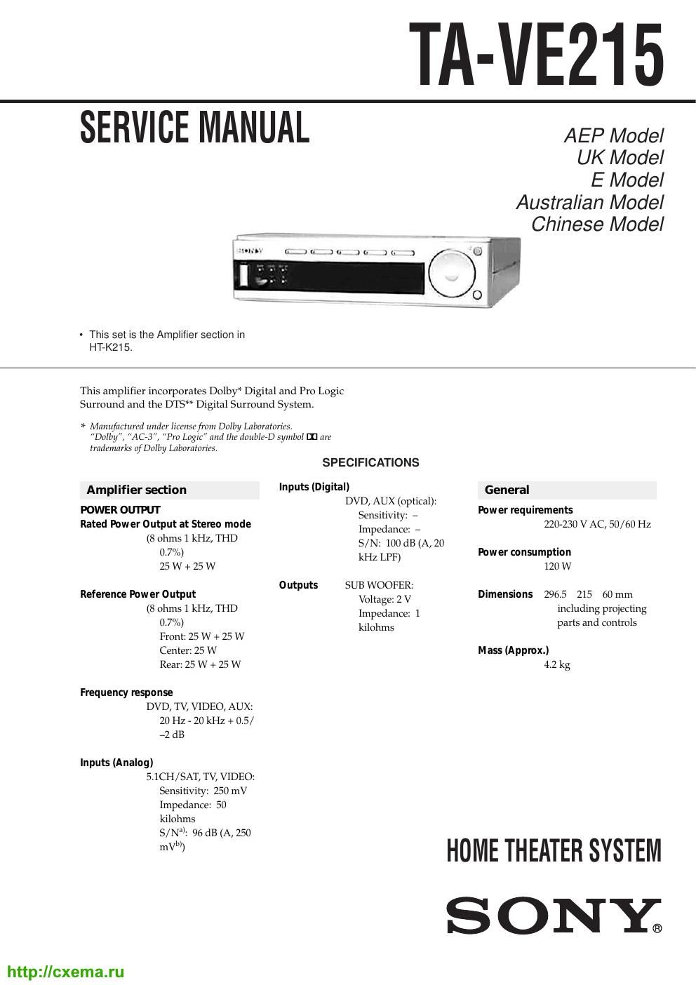
TA-VE215

SERVICE MANUAL

AEP Model

UK Model

E Model
Australian Model
Chinese Model

- This set is the Amplifier section in
HT-K215.

This amplifier incorporates Dolby* Digital and Pro Logic
Surround and the DTS" Digital Surround System,

5* Manufactured under licensefrom Dolby Laboratories.
Dolby, AC3", Pro Logic and the doubleD symbol DCI are
trademarks of Dolby Laboratories.

SPECIFICATIONS
Amplifier section 'PUts (Digita') General
DVD, AUX (optical):
POWER OUTPUT Sensitivity: _ Power requirements
Rated Pow er Output at Stereo mode Impedance: _ 220-230 V AC, 50/60 Hz
(8 Ohms 1 kHZr THD S/N: 100 dB (A, 20 .
0.7 /o) kHz LPF) Pow er consumption
25 W + 25 W 120 W
Outputs SUB WOOFER:
Reference Power Output Voltage: 2 V Dimensions 2965 215 60 mm
(8 ohms 1 kHz, THD Impedance: 1 including projecting
0.7%) kilohms parts and controls
Front: 25 W + 25 W
Center: 25 W Mass (Approx.)

Rear: 25 W + 25 W

Frequency response
DVD, TV, VIDEO, AUX:
20 Hz - 20 kHz + 0.5/
-2 dB

Inputs (Analog)
5.1CH/SAT, TV, VIDEO:
Sensitivity: 250 mV
Impedance: 50
kilohms
S/Nal: 96 dB (A, 250

42 kg

HOMETHEATER SYSTEM
S O NY®

http:llcxema.ru

Page 2

TABLE OF CONTENTS

1_ GENERAL ......................................................................... 3
2_ TEST MODE ................................................................... 4
3. DIAGRAMS .......................

3-1. Circuit Boar Location .
3-2. Block Diagram

7 MAIN Section 7

7 POWER Section 7
3-3. Printed Wiring Boards 7 DIGITAL Section
34. Schematic Diagram 7 DIGITAL Section (1/2)
3-5. Schematic Diagram 7 DIGITAL Section (2/2)
36. Printed Wiring Boards

oowqo

7 OPTICAL / SIGNAL BRIDGE Section 7 ----------- 11
3-7. Schematic Diagram
7 SIGNAL BRIDGE Section 7 ------------ . 11

.12
~13
-14
.15

3e8. Schematic Diagram 7 DISPLAY Section 7
3-9. Printed Wiring Boards 7 DISPLAY Section 7
3-10. Printed Wiring Boards 7 MAIN Section 7
3-11. Schematic Diagram 7 MAIN Section (1/2) 7

3-12. Schematic Diagram 7 MAIN Section (2/2) 7 . 16
3-13. Printed Wiring Boards 7 POWER Section - 17
3-14. IC Pin Function Description ----------------- I 18
3_15_ 1C Block Diagrams .................................................... 19
4. EXPLODED VIEWS .20
5. ELECTRICAL PARTS LIST ------------------------------------- 22

' Grounding connection at the two points between the MAIN
board and the chassis is necessary while the main power
to the MAIN board is turned on.

- Jig is used to inspect the DIGITAL board.

1. Between the DIGITAL board CNSSO7 and OPTICAL board CNP807

8 P/L=300 (A-2501-2060A)

2. Between the DIGITAL board CNSSOS and SIGNAL BRIDGE

board CNSSOZ

18 PIL=3OU (A-2501-207-A)

Flexible Circuit Board Repairing

- Keep the temperature of soldering iron around 270C
during repairing.

- Do not touch the soldering iron on the same conductor of the
circuit board (within 3 times).

- Be careful not to apply force on the conductor when soldering
or unsoldering.

2
http://cxema.ru

SAFETY-RELATED COMPONENT WARNING!!

COMPONENTS IDENTIFIED BY MARKA OR DOTTED LINEWITH
MARK A ON THE SCHEMATIC DIAGRAMS AND IN THE PARTS
LIST ARE CRITICAL TO SAFE OPERATION. REPLACE THESE
COMPONENTS WITH SONY PARTS WHOSE PART NUMBERS
APPEAR AS SHOWN IN THIS MANUAL OR IN SUPPLEMENTS
PUBLISHED BY SONY.

SfigfiééBJSEflfiéfiéfl

ElfifiliffiflfififlAfiififiiflfilfifigfififlfifiéfilfi
LEEESEQHEJO fifiifififiifii$¥fitifififtafififli¢§
fiflfiflifificififltfififiiflze

EEfifiIEiEfiXfifiWfifiifiIE-fiifiidfittflfia]
fif§¥fifi§£-¥ia Eiifiifiigfififififififiifiikfi
Ed. fiifiIfflEifiEfiIEo