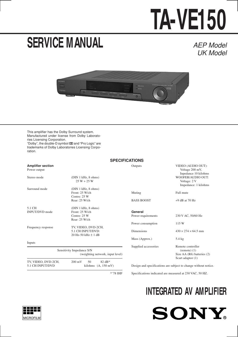
Sony ta ve 150 service manual
This is the 29 pages manual for sony ta ve 150 service manual.
Read or download the pdf for free. If you want to contribute, please upload pdfs to audioservicemanuals.wetransfer.com.
Extracted text from sony ta ve 150 service manual (Ocr-read)
Page 1
Ð 2 Ð TABLE OF CONTENTS 1. GENERAL .................................................................. 3 2. DISASSEMBLY ......................................................... 4 3. TEST MODE .............................................................. 5 4. DIAGRAMS ................................................................. 6 4-1. Notes for Printed Wiring Board and Schematic Diagram .................................................. 7 4-2. Printed Wiring Board Ð MAIN Section Ð ...................... 11 4-3. Schematic Diagram Ð MAIN Section (1/2) Ð ................ 13 4-4. Schematic Diagram Ð MAIN Section (2/2) Ð ................ 15 4-5. Printed Wiring Boards Ð PANEL Section Ð .................. 17 4-6. Schematic Diagram Ð PANEL Section Ð ....................... 19 4-7. Printed Wiring Boards Ð POWER Section Ð ................. 21 4-8. Schematic Diagram Ð POWER Section Ð ..................... 23 4-9. IC Pin Function Description ........................................... 25 5. EXPLODED VIEWS ................................................ 27 6. ELECTRICAL PARTS LIST ............................... 29 Notes on chip component replacement ¥ Never reuse a disconnected chip component. ¥ Notice that the minus side of a tantalum capacitor may be dam- aged by heat. SAFETY-RELATED COMPONENT WARNING!! COMPONENTS IDENTIFIED BY A ! MARK ON THE SCHEMATIC DIAGRAMS, EXPLODED VIEWS AND IN THE PARTS LIST ARE CRITICAL TO SAFE OPERATION. REPLACE THESE COMPO- NENTS WITH SONY PARTS WHOSE PART NUMBERS APPEAR AS SHOWN IN THIS MANUAL OR IN SUPPLEMENTS PUB- LISHED BY SONY.
Page 2
Ð 3 Ð SECTION 1 GENERAL 1I /u button 23 STEREO indicator 3NORMAL indicator 4WIDE indicator 5PHANTOM indicator 6Remote sensor 7Display window 8SIMULATED indicator 9C. STUDIO indicator !¼PRO LOGIC indicator 15.1 CH INPUT/DVD jacks 2DVD 2 CH jacks 3VIDEO jacks 4TV jacks Location of controls Ñ Front view Ñ Ñ Rear view Ñ 1 !¢ !° !¤ !¦ !¥ !» 2 3 4 5 6 7 8 9 !¼ !Á !ª !£ !ÁBASS BOOST indicator !ªMUTING indicator !£MASTER VOLUME dial !¢CENTER MODE button !°TV button !¤VIDEO button !¦DVD, 2 CH button !¥5.1 CH INPUT, DVD button !»SURROUND MODE button 1 2 3 4 5 6 7 8 5WOOFER jack 6FRONT SPEAKERS terminals 7REAR SPEAKERS terminals 8CENTER SPEAKER terminals