Sony ta s 7 av service manual

This is the 28 pages manual for sony ta s 7 av service manual.
Read or download the pdf for free. If you want to contribute, please upload pdfs to audioservicemanuals.wetransfer.com.

Page: 1 / 28
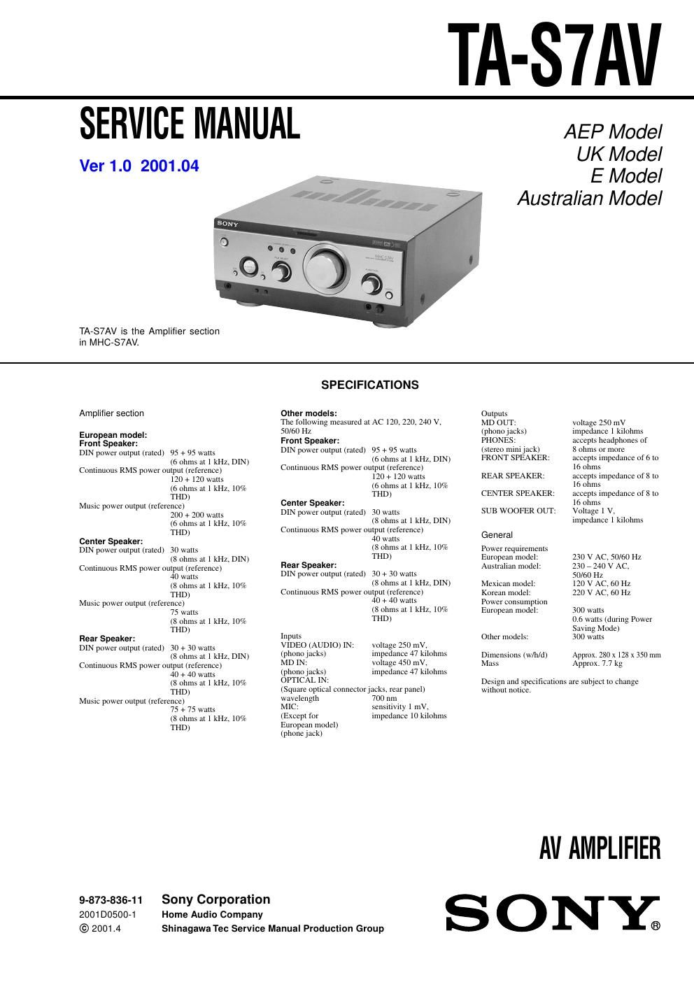
sony ta s 7 av service manual

Extracted text from sony ta s 7 av service manual (Ocr-read)


Page 1

TA-SlAV

SERVICE MANUAL

Ver 1.0 2001.04

TA-S7AV is the Amplifier section
in MHC-S7AV.

AEP Model

UK Model

E Model
Australian Model

Amplifier section

European model:
Front Speaker:
DIN power output (rated) 95 + 95 watts
(6 ohms at I kHz, DIN)
Continuous RMS power output (reference)
120 + 120 walls
(6 ohms at 1 kHz, 10%
THD)
Music power output (reference)
200 + 200 walls
(6 ohms at I kHz, 10%
THD)
Center Speaker:
DIN power output (rated) 30 watts
(2; ohms at I kHz, DIN)
Continuous RMS power output (reference)
40 walls
(8 ohms at 1 kHz, 10%
THD)
Music power output (reference)
75 walls
(8 ohms at I kHz, 10%
THD)
Rear Speaker:
DIN power output (rated) 30+ 30 watts
(2; ohms at I kHz, DIN)
Continuous RMS power output (reference)
40 + A0 walls
(8 ohms at 1 kHz, 10%
THD)
Music power output (reference)
75 + 75 walls
(8 ohms at I kHz, 10%
THD)

9-873-836-11 Sony Corporation
2001D0500-1 Home Audio Company
© 2001.4

Shinagawa Tec Service Manual Production Group

SPECIFICATIONS

Other models:
The following measured at AC 120, 220, 240 Vs
50/60 HZ
Front Speaker:
DIN power output (rated) 95 + 95 watts
(6 ohms at I kHz. DIN)
Continuous RMS power output (reference)
120 + 120 walls
(6 ohms III I kHZi 10%
Tl-lD)
Center Speaker:
DIN power output (rated) 30 watts
(8 ohms at I kHZi DIN)
Continuous RMS power output (reference)
40 walls
(8 ohms at 1 kHz) 10%
TI-ID)
Rear Speaker:
DIN power output (rated) 30 + 30 watts
(8 ohms at I kHz. DIN)
Continuous RMS power output (reference)
40 + A0 walls
(8 ohms III I kHZi 10%

THD)
Inputs

VIDEO (AUDIO) IN: voltage 250 mv,
(phoiio Jacks) impedance 47 kIlohms

MD IN: voltage 450 mV,
(phono Jacks) impedance 47 kilohins
OPTICAL IN:

(Square optical connector tacks rear panel)

wavelength 700 nm
MIC: sensitivity I invc
(Except tor impedance lo kilohms
European model)

(phone Jack)

Outputs

MD OUT: voltage 250 mV

(phono Jacks) impedance I kilohms

PHONES: accepts headphones of

(stereo mini Jack) 8 ohms or more

FRONT SPEAKER: accepts impedance ot a to
16 ohms

REAR SPEAKER: accepts impedance of x to
lo ohms

CENTER SPEAKER. accepts impedance ot It to
16 ohms

SUB WOOFER our: Voltage I v,

impedance I kilohms

General

Power requirements
European model:
Australian model:

230 V AC, 50/601-[1
230 r 240 V AC.
50/fi0 HZ

l20 V AC, 60 HZ
220 V AC, 60 HZ

Mexican model:
Korean model:
Power consumption
European model: 300 watts

0.6 watts (during Power
Saving Mode)

Other models: 300 watts
Dimensions (w/h/d) Approx. 280 x 128 x 350 mm
Mass Approx. 7.7 kg

Design and specifications are Subject to change
without notice.

AV AMPLIFIER

SONYs

Page 2

TA-S7AV

TABLE OF CONTENTS

1. SERVICING NOTES ............................................... 3
2. GENERAL ................................................................... 4
3. DISASSEMBLY
3- 1. Disassembly Flow ........................................................... 5
3721 Cover ................... 6
373. Front Panel Section . 6
3-4. Back Panel (AV) Section 7
3-5 FRONT AMP Board ....................................................... 7
4. TEST MODE .............................................................. 8
5. DIAGRAMS
5-] Note for Primed Wiring Boards

and Schematic Diagrams ................................................ 10
572. Printed Wiring Boards 7 FRONT AMP Section 7 . . 11
573. Schematic Diagram 7 FRONT AMP Section (1/2) 12
5-4. Schematic Diagram 7 FRONT AMP Section (2/2) 7 13
5751 IC Pin Function Description ........................................... 14
56. Printed Wiring Board

7 SURROUND AMP Section 7 14
5-7. Schematic Diagram

7 SURROUND AMP Section 7 ...................................... 15
578. Printed Wiring Boards 7 CONTROL Section 7 16
579. Schematic Diagram 7 CONTROL Section 7 17
5-10. Printed Wiring Boards 7 POWER Section 7 18
51 1. Schematic Diagram 7 POWER Section 7 ..................... 19
6. EXPLODED VIEWS
6-1. Cover Section ....... 20
6-2. Front Panel Section . 20
673. Chassis Section 21
7. ELECTRICAL PARTS LIST ............................... 22

SAFETY-RELATED COMPONENT WARNING I!

COMPONENTS IDENTIFIED BY MARK A OR DOTTED
LINE WITH MARK A ON THE SCHEMATIC DIAGRAMS
AND IN THE PARTS LIST ARE CRITICAL T0 SAFE
OPERATION. REPLACE THESE COMPONENTS WITH
SONY PARTS WHOSE PART NUMBERS APPEAR AS
SHOWN IN THIS MANUAL OR IN SUPPLEMENTS PUB-
LISHED BY SONY.