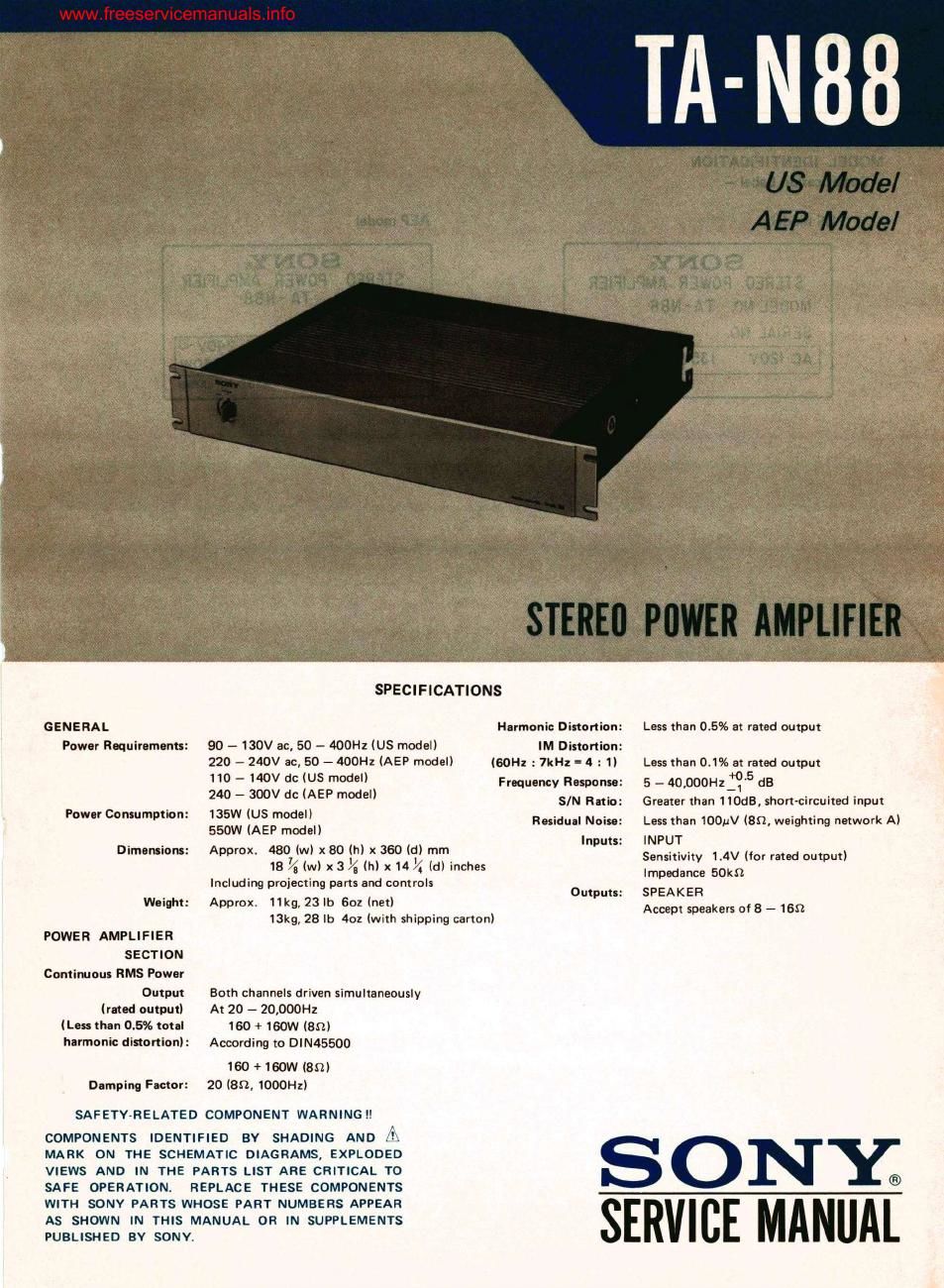
Sony ta n 88 pwr service manual
This is the 40 pages manual for sony ta n 88 pwr service manual.
Read or download the pdf for free. If you want to contribute, please upload pdfs to audioservicemanuals.wetransfer.com.
Extracted text from sony ta n 88 pwr service manual (Ocr-read)
Page 1
G ENERA L
Puwor Require-nuts:
Paw-r Consumption:
Dirnlnsions:
Wainht:
POWER AMPLIFIER
SECTION
Continuous HMS Paw-r
Output
(rated output)
(Less than 0.5% total
harmonic istortion):
Damping Factor:
SPECIFICATIONS
Harmonic Distortion:
IM Distortion:
90 - 130V ac, 50 - 400Hz (US model)
220 - 240V ac, 50 - 400Hz (AEP model)
no --140v dc (us model)
240 7 300V dc (AEP model)
135W (U5 model)
550W (AEP model)
Approx. 430 (w) x 60 (h) x 360 (d) mm
18 7/3 (w) x3 I/glhl x145 (d) inches
Including projecting parts and controls
Approx: 11kg, 23 lb 602 (net)
13kg, 28 lb 402 (with shipping carton)
I60! : 7kHz '4 :1)
Outputs:
Both channels driven simultaneously
At 20 - 20,000Hz
160 + 160W (8!!)
According to DIN45500
160 + 160W (8m
20 (an, 1000Hz)
Frequency Response:
SIN Ratio:
Residual Noise:
Inputs:
Less than 0.5% at rated output
Less than 0.1% at rated output
5 - 40,000sz15 dB
Greater than 110dB, short-circuited input
Less than 100ml (80, weighting network A)
INPUT
Sensitivity 1.4V (for rated output)
Impedance SUkfl
SPEAKER
Accept speakers of8 - 16D
SAFETV~RELATED COMPONENT WARNING !l
COMPONENTS IDENTIFIED BY SHADING AND Iii
MARK ON THE SCHEMATIC DIAGRAMS, EXPLODED
VIEWS AND IN THE PARTS LIST ARE CRITICAL TO
SAFE OPERATION. REPLACE THESE COMPONENTS
WITH SONY PARTS WHOSE PART NUMBERS APPEAR
AS SHOWN IN THIS MANUAL OR IN SUPPLEMENTS
PUBLISHED BY SONY.
5w
SERVICE MANU L
Page 2
www.free ervicemanualsinfo
TA-N88 'I'A-N88
SECTION 1
OUTLINE
MODEL IDENTIFICATION
- Specification Label -
US model
SONY@
STEREO POWER AMPLIFIER
MODEL NO. TA' N88
AEP model
SONY®
STEREO POWER AMPLIFIER
MODEL N0. TA-N88
SERIAL N0.
1-1.
SERVICING NOTE
I. This set is utilizing pulse circuitry, Use an oscillo-
scope having a bandwidth of wider than lOMHz.
2. Be sure to discharge current completely before
starting repair. This set uses V-FETs. Also this set
utilizes l40-V voltage in the power supply and
tIZO-V voltage in the amplifier section. Ac-
ponent lead wires or pattern foils are inadvertent-
ly shorted out by a screwdriver or a soldering
iron due to the redidual charge in the power-
supply capacitors even when the power is turned
off.
To prevent the damage of these components,
be sure to discharge electrolytic capacitors, after
turning the power off, in the power supply as
SERIAL N0. cordingly not only V-FETs but also many other shown in Fig. 1 every time the check or repair is
'2 ®® AC 220, 24OV~ v . .
AC 0V |35W GOHI ® .Q. 50/60Hz 550W _ components my easily be damaged if any com- required,
MADE IN JAPAN "ADE IN JAPAN
Note: All rumors are about 10 ohms. m terminals
across fins of of electrolytic capacitor C501
transistors
'- " I
T _ |
I 1 across fins of
| | transistor:
I |
' I
I I
' I
|
l |
I I
l I
L __ _ J
|_ _ _ _J
. I across terminals
2:32:27": 5 of electrolytic
capacitor €503 capacrtar 0502
Fig. 1
3. Power Supply Checking
a) t78-V voltages should present on C502 and
C503. Voltage adjustment can be made by
RT401.
b) If voltages on C502 and C503 cannot be
adjusted by RT40l and higher voltages of
about ilOOV are present, check the switching 156Vp-p
transistor Q401 in the power supply.
c) If voltages do not present on C502 and C503, 2115
check Q409 through 0412 of the inverter (SDOkHz)
circuit in the power supply.
4. Power Amp Checking
3) Check waveform at the drains of V-FETs
of each channel. The following waveform
should be obtained.
_2_