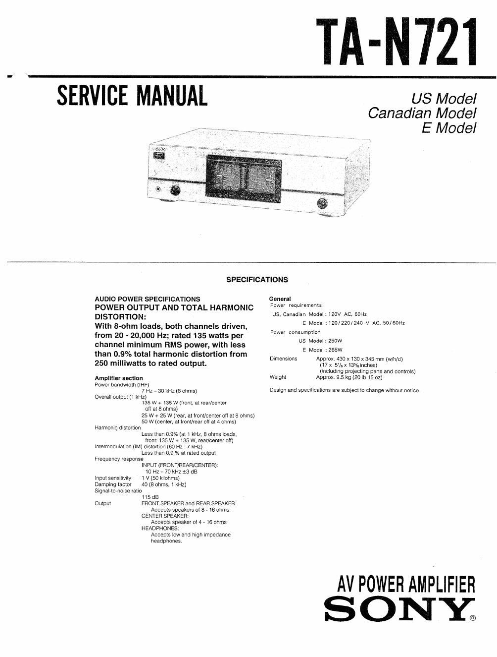
Sony ta n 721 service manual
This is the 16 pages manual for sony ta n 721 service manual.
Read or download the pdf for free. If you want to contribute, please upload pdfs to audioservicemanuals.wetransfer.com.
Extracted text from sony ta n 721 service manual (Ocr-read)
Page 1
TA-N721
SERVICE MANu'ii'L' USMode,
Canadian Model
E Model
SPECIFICATIONS
AUDIO POWER SPECIFICATIONS General _
POWER OUTPUT AND TOTAL HARMONIC PMS" requ'remens
DISTORTION: us, Canadian Modei:120V Ac GOHZ
With 8-ohm loads, both channels driven, E W 1 120/220/240 V AC» 50/5on
from 20 ~ 20,000 Hz; rated 135 watts per PM °°S°"°"
US Model : 250W
channel minimum RMS power, With less E Mode|1265W
than 0.9% total harmonic distortion from
. _ Dimensmns prox. 430 x 130 x 345 mm w/hld
250 mllliwatts to rated output. A{(917 x 5v8 x 135/sinches) ( )
(including projecting parts and controis)
Ampfifier semen Weight Approx. 9.5 kg (2011) 15 02)
Power bandwidth (IHF)
7 Hz _ 30 kHz (3 ohms) Design and specifications are subject to change without notice.
Overall output (1 kHz)
135 w + 135 w (rront, at rear/center
off at 8 ohms)
25 W + 25 W (rear. at front/center off at 8 ohms)
50 w (center. at front/rear 0" at 4 ohms)
Harmonic distortion
Less than 0.9% (a! 1 kHz. 8 ohms loads,
front 135 w + 135 w, rear/center off)
intermodulatton (IM) diSIOnIOfl (60 Hz - 7 kHz)
Less than 0.9 % at rated output
Frequency response
iNPUT (FRONT/REAR/CENTER),
10 Hz- 70 kHZtS dB
input sensitivity 1 V(50 kllohrns)
Damping iactor 40 (8 ohms, 1 kHz)
Signatho-noise ratio
1 15 dB
Output FRONT SPEAKER and REAR SPEAKER.
Accepts speakers oi 8 . 16 ohms
CENTER SPEAKER:
Accepts speaker oi 4 - 16 ohms
HEADPHONES:
Accepts low and high impedance
headphones
AV POWER AMPLIFIER
SONY;
Page 2
I
TA- N721
TABLE OF CONTENTS
Section Title Page
1, GENERAL ......................................... 3
2. ELECTRICAL MEASUREMENTS -------------------- 5
3. DIAGRAMS
3- 1. Semiconductor Lead Layouts ~~~~~~~~~~~~~~~~ 5
372, Printed Wiring Boards ....................... 5
3- 3. Schematic Diagram ........... . ................ 9
34. Circut Boards Location ~~~~~~~~~~~~~~~~~~~~~~~ 12
3»5, 1C Block Diagrams ......... .. ......... 12
4. EXPLODED vrsws ~~~~~~~~~~~~~~~~~~~~~~~~~~~~~~ 13
s. ELECTRICAL PARTS LIST ~~~~~~~~~~~~~~~~~~~~~~~~ 15
MODEL IDENTIFICATION
- Specification Label -
SONY.
MODEL NO. TA-N72l
STEREO POWER AMPLIFIER
//////////////////////////
SERIAL NO.
MADE IN JAPAN
I
US Model : AC: 120V 60Hz 250W
Canadian Model : AC : 120V 60Hz 370VA
E Model : AC : 120/220/240V~50/80Hz 265W
SAFETYRELATED COMPONENT WARNING
COMPONENTS IDENTIFIED BY MARK A OR DOTTED
LINE WITH MARK A ON THE SCHEMATIC DIAGRAMS
AND IN THE PARTS LIST ARE CRITICAL TO SAFE
OPERATION. REPLACE THESE COMPONENTS WITH
SONY PARTS WHOSE PART NUMBERS APPEAR AS
SHOWN IN THIS MANUAL OR IN SUPPLEMENTS PUB-
LISHED BY SONY.
SAFETY CHECK-OUT
After correcting the original service problem,
perform the following safety check before releasing
the set to the customer:
Check the antenna terminals, metal trim, metallized
knobs, screws, and all other exposed metal parts for
AC leakage. Check leakage as described below.
L EAKAG E TEST
The AC leakage from any exposed metal part to
earth ground and from all exposed metal parts to any
exposed metal part having a return to chassis, must
not exceed 0.5 mA (500 microampers). Leakage
current can be measured by any one of three
methods.
I. A commercial leakage tester, such as the
Simpson 229 or RCA WT-540A. Follow the
manufacturers instructions to use these instru-
ments.
2. A battery-operated AC milliammeter. The Data
Precision 245 digital multimeter is suitable for
this job.
3. Measuring the voltage drop across a resistor by
means of a VOM or batteryoperated AC volt-
meter. The "limit indication is 0.75V, so
analog meters must have an accurate low-
voltage scale. The Simpson 250 and Sanwa
SH-63Trd are examples of a passive VOM that
is suitable. Nearly all battery operated digital
multimeters that have 3 2V AC range are
suitable. (See Fig. A)
To Exposed Metal
Part: on Set
_[ AC
015% 7.5m / voltmeter
(0.75 v)
- 1-
._I
"7' Earth Ground
Fig, A. Using an AC voltmeter to check AC leakage.
ATTENTION AUACOMPOSANT AYANT RAPPORT
LAA SECURITE!
LES cowosmrs IDENTIFIES PAR UNE MAROUE A
sun LES DIAGRAMMES scuéMArloues ET LA LISTE
DES PIECES sour cmriouzs POUR LA sécumré
DE FONCTIONNEMENT. NE REMPLACER ces coM-
POSANTS QUE PAR DES PIECES SONY DONT LES
NUMéRos som DONNES DANS cs MANUEL ou
DANS LES SUPPLEMENTS Puaués PAR sonv.