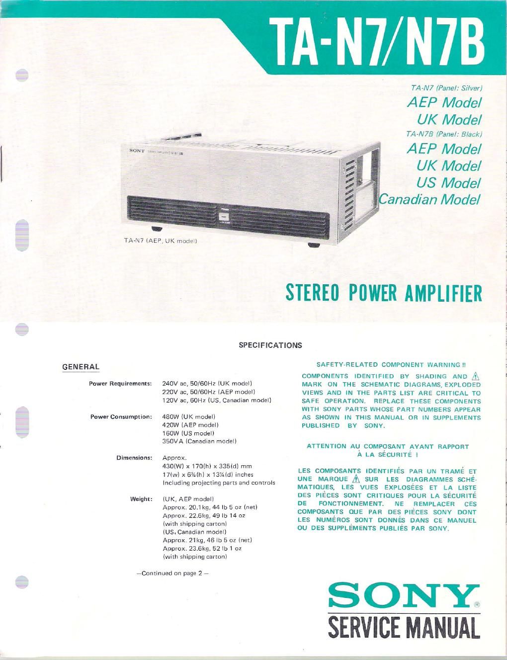
Sony ta n 7 b service manual
This is the 24 pages manual for sony ta n 7 b service manual.
Read or download the pdf for free. If you want to contribute, please upload pdfs to audioservicemanuals.wetransfer.com.
Extracted text from sony ta n 7 b service manual (Ocr-read)
Page 2
TA-N7/N7B
POWER AMPLIFIER SECTION
Continuous R MS
Power Output:
{Less than 001% THD)
Power Bandwidth:
Damping Facto .
Harmonic Distortion:
Both channels driven simultaneously
At ZIP-20,000 Hz
100W +100W(8fl)
According to DIN 45500IAEP,UKnIDde|I
100W + 100W (8S1)
5-35.000 HZ (80), IHF (AEP,UK model)
IM Distortion:
ISOHZ: 7kH2 : 4:1]
Frequency Response:
S/N Ratio:
Residual Noise:
Less than 0.01% at rated output
Less than 0008% at 1W/10W output
DC7100,000HZ :2 dB (DIRECT INPUT)
67100,DOOHZ 1°, dB (C COUPLED INPUT)
Greater than 120 dB, short-circuited input
Less than 0.024mV (8Q) weighting
100 (89.. IkHz) networISL
Less than 001% at rated output Inputs: S ' 'vIty
Less than 0008% at IW/IOW output DIRECT: l
C COUPLED 13V j 50m
Less than 0.0l % at 250mW-rateo output 13H: cut vloff (for rated output)
(US, Canadian model) frequency) L
OutputS: SPEAKER terminals:
0 MODEL IDENTIFICATIONS
- Specification Labe/ -
AEP model (TA-N7)
Accept speakers of 8:1 or more
UK modal lTA-N7I
I STEREO AMPLIFIER STEREO AMPLIFIER
SON-I MODEL NO. TA-N7 SONY MODEL NO TA- N7
AC 220v m 50/60Hz 420w . 240v ~50/60Hz 450w
SERIAL NO. SERIAL N0
L MADE IN MADE IN
AEP model (TA-N73) UK model (TA-N75)
T
STEREO AMPLIFIER _ STEREO AMPLIFIER
SONY'I MODEL N0. TA -N 79 SONY MODEL NoI TA- N 78
Ac 220v I» 50/60Hz 420w AC 240v w 50/60Hz aeow
SERIAL N0. SERIAL N0,
MADE IN L MADE IN
US model (TA-N73) Canadian model (TA-N73)
I STEREO AMPLIFIER N .7 STEREO AMPLIFIER
SONY MODEL NO. TA-N7B SO Y MODEL N0. TA-N7B
Ac IZOV SOHI Ieow AC Izov 60H: 350w:
SERIAL NO, SERIALN
MADE IN MADE IN
SERVICING NOTES
I This set uses bipolar transistors and V-
FETs in cascade circuit to maintain
stable biasing. When replacing the
three P-channel V-FETs 251(60 and/or
the three N~channe1 V-FETs 28118
in each channel, use three matched
ones which have the same Vp (pinch-
off voltage)~rank figure printed on
them as shown below, The fluctuation
of the Vp rank of the three can be
acceptable on oneqank-difference
basis.
0 Two kinds of hexagonal~socket screw-
drivers are required for the following
removal.
. top cover removal
: side plate removal