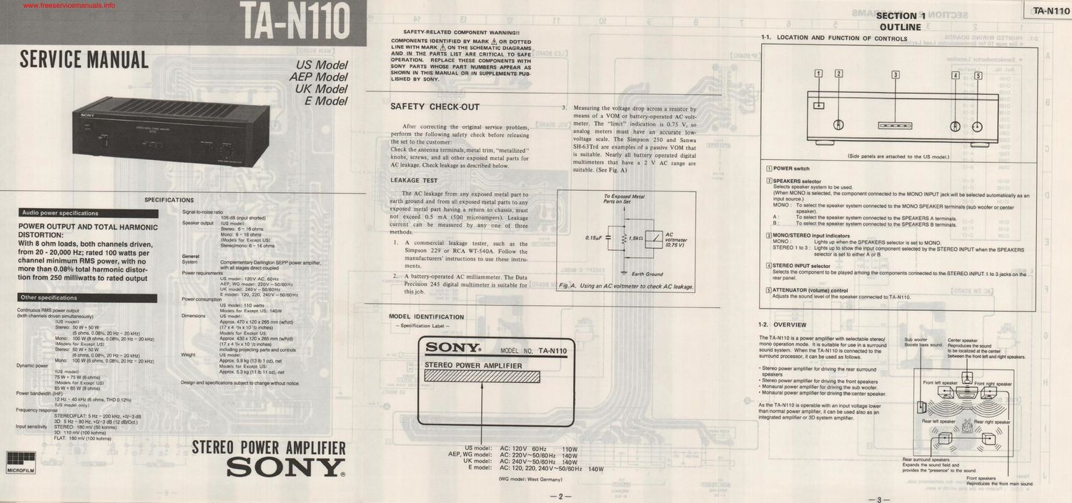
Sony ta n 110 pwr service manual
This is the 6 pages manual for sony ta n 110 pwr service manual.
Read or download the pdf for free. If you want to contribute, please upload pdfs to audioservicemanuals.wetransfer.com.
Extracted text from sony ta n 110 pwr service manual (Ocr-read)
Page 1
TA-N11O
SECTION 1
OUTLINE
SAFETVRELATED COMPONENT WARNING" 1-1. LOCATION AND FUNCTION OF CONTROLS
COMPONENTS IDENTIFIED BV MARK A OR DOTTED
LINE WITH MARK A ON THE scHEMATIc OIAGRAMS
AND IN THE PARTS LIST ARE CRITICAL TO SAFE
OPERATION. REPLACE THESE COMPONENTS WITH
SONY PARTS WHOSE PART NUMBERS APPEAR AS
SHOWN IN THIS MANUAL OR IN SUPPLEMENTS PUB- m '2 E] E E5]
LISHED BY SONV.
' , TA-Nll
SERVICE MANUAL
US Model
AEP Model
UK Model
E Model
SAFETY CHECK-OUT 3. Measuring the voltage drop across a resistor by
means of a VOM or battery-operated AC volt-
meter. The limit indication is 0.75 V, so ®
analog meters must have an accurate IOW<
voltage scale The Simpson 250 and Sanwa E cg
SH-63Trd are examples of a passive VOM that
is suitable. Nearly all battery Operated digital
multimeters that have a 2 V AC range are
suitable. (See Fig. A)
After correcting the original service problem,
perform the following safety check before releasing
the set to the customer:
Check the antenna terminals,metal trim, metallized
knobs, screws, and all other exposed metal parts for
AC leakage. Check leakage as described below.
(Side panels are attached to the US model.l
III POWER switch
E] SPEAKERS selector
LEAKAGE TEST
Selects speaker system to be used.
(When MONO is selected, the component connected to the MONO INPUT jack will be selected automatically as an
The AC leakage from any exposed metal part to To Exposed Metal input source.)
SPECIFICATIONS earth ground and from all exposed metal parts to any Part: on Set MONO : To select the speaker system connected to the MONO SPEAKER termlnals (sub woofer or center
exposed metal part having a return to chassis, must A Tiestlzgtthe speaker system connected to the SPEAKERS Atermtnals
. . . . Si naI-tomoise ratio ' I
Audio power specttlcations g 105 dB in m shorted not exceed 0-5 "1A (500 mlcroampers). Leakage B: To select the speaker system connected to the SPEAKERS Bterrninalsl
S [p] ) cutent c n be measu d by a y on of th
peaker output (Us model r a re 11 e ree
POWER OUTPUT AND TOTAL HARMONIC Stereo: 6 - l6 ohms methods, AC @MONO/STEREO input Indlcatore
DISTORTION' Mono: 8 - 16 ohms 0- 75HF g 15k / voltmeter MONO : Lights up when the SPEAKERS selector is set to MONO.
_ ' _ IMOdels Ior Excem US) l . A commercial leakage tester, such as the 7-75 VI STEREO 1 IO 3 : Lights up to show the input component selected by the STEREO INPUT when the SPEAKERS
With 8 ohm loads, both channels driven, stereo/nonos- 16 ohms Simpson 229 or RCA WT-54OA. Follow the - l 59mgr is 38., he... a
from 20 ' 20l0°o HZ; rand 100 watts per General manufacturers' instructions to use these instru- ESTEREO INPUT selector
_ _ . - I'fi
channel minimum RMS power, WIth no System gmgmgzigflmmflp Power 8mm at ments. 4_ Emh c u d Selects Ihe component to be played among the components connected to the STEREO INPUT l to a jacks on the
' - , T no 11
more than 0.08 /-o total harmonic distor P°w°°"""°"'f.s . 2 v AC 60H 2. A batterwpmted AC mimmmem The Data rear panel,
tIOn from 250 mlIIIwatIS to rated output AE mg 510;: I: 226v _510 IGOHz precision 245 digital multimeter is suitable {0]- Fig, A, Using an AC voltmeter to check AC leakage. EIATTENUATOR (volume) control
UK model: 240v - 50/60Hz this job_ Adjusts the sound level at the speaker connected to TA-N110.
E model: I20, 220, 240v ~5Cl/60H2
Other specifications Poweroonsumption
US model: 110 watts
Conflnuous RMS power outpul Models for Except Us: 140W
both channels driven slmultaneousl Dimensions US model:
( (Us model) Y) Approx. 470 x 120 x 265 mm (th/d)
[17 x 4 /4 x10l2lhches)
Models Ior Except US:
Approx. 430 x 120 x 265 mm (wlhld)
MODEL IDENTIFICATION
7 Specification Label -
SONYo
1-2. OVERVIEW
Stereo: 50 W a 50 W
(6 ohms. 0.08%. 20 Hz ~ 20 kHzl
Mono: 100 W (8 ohms. 0.08%. 20 Hz - 20 kHz) .
(Models Ior Except usl 7 X 4 3/ " 1° 72 mm)
Stereo: 50 W + 50 W including projecting parts and controls
(6 ohms. 0.08%. 20 Hz A 20 kHz) Weight 5 "m5
Approx. 5.9 kg (13 lb 1 oz). net
The TA-N1 10 is a power amplilier with selectable stereo] Sub wooler Center speaker
mono operation mode, It is suitable for use in a surround 30053 5355 50""3- Reproduce?» the sound
sound system. When the TA-Nl 10 is connected to the 0 be 03le 3' "'9 camel
surround processor. it can be used as follows between "9 Irontlelt and "9h'5993ke's'
MODEL N0. TA-N110
Mono: 100 W (6 ohms. 0.08%. 20 Hz - 20 kHz) STEREO POWER AMPLI HER - Stereo power amplifier Ior driving the rear surround
Dynamic power Models for Except'US: speakers E
(7:3??ng 5 h Approx. 53 kg (11 b 11 oz). net / / - Stereo power amplilier Ior driving the front speakers From Ieh speaker _ Front right speaker
+ 0 ms _ t . . .
l Mode for Except J5, Design and specifications subject to change without notice. Monaural power amplifier for derlng the sub wooter. at
_-_ -
ux! E la:
\\\\:xE€//
ivy
- Monaural power amplifier for driving the center speaker.
85 W + 85 W (3 ohms)
Power bandwidth (IHF)
12 Hz - 40 kHz (6 ohms. THD 012%)
IUS model only)
As the TA-N110 is operable with an input voltage lower
than normal power amplifier. it can be used also as an
Frequency response integrated amplifier or 3D system amplifier. Rear left speaker Rear right speaker
STEREO/FLAT: 5 Hz - 200 kHz. +0l'3 dB \ /
3D: 5 Hz - 80 Hz. +0l-3 dB (12 dBIOct.) /// \\ // \\
Input sensitivity STEREO: 15(1ther kohms)
SD: 110 mV (100 kohms)
FLAT: 180 mV 1100 kohms)
//
///
\ 7/
STERE POWER AMPLIFIER USmodel: AC:120V 60Hz 110w .
AEP, WG model: AC: 220V~50l60Hz I40W Rear surround speakers
UK model: Ac: 24ov~50/60Hz 140w wards the _5°"d tel? and
S O N Y E model: AC: 120, 220, 240V~50/60HZ 140W provtdes the presence to the sound.
ak r
MICROFILM ® 33:32:"; Iront main sound
(we model: West Germany)
Page 2
MsewicemanualsigEc-HON 2v DIAGRAMS
1 I 2 I 3 I 4 J 5 I 6 I 7 I 8 I 9 I 10 I 11 I 12 I 13 I 14 I 15 I 16 I 17 I 18 I 19 I 20 I 21 22
2-1. PRINTED WIRING BOARDS
0 See pigs 10 fat Semtconductor Load LIYOII'II. I. ______________________________________________ 1A.---__.1
m I a A
A o Semiconductor Location [SF BOARD [LEO BOARD] - u: m 0 I [MAIN BOARD] I I
Roi. No. Locution .1- 950 I r
.l I
- 0I0| D-I8 I u ' .
DIOZ 0-11 . I I
0I03 H-Is I 1 I
DIM B-l8 ' I
B was G-IB g-I IE I
D106 E-I8 I "'
0m c-n I
-I 0152 G-l8 :
D30| E-Iz VOL BOARD I
0302 [5-14 u 0-4, G
0501 A-I2 ' . I
C 0502 A-IZ I I \
0503 A-l3 I
_ 0504 A-I3 I I m
IOIIO I I
ICIOI E-l6 INPUT B >" an
ICU)? C-l8 m n
D IOIO3 H-Zl 2:: I
Icum 6-22 I: m 4
10005 0-2I a . I I
I
- OIOI D-l7 I II
QIOZ F-IB r - H I CI
E 0104 c-n | I
I swz """"
|
I . ~
I m 2 I ___
- I nan 'ov I 7 1 610
E MODEL _l W" | b
F - I grew E MODEL _I - -
- me
F I rsoI I I FEVER VIE-2mm»: I
I [AC SW BOARD) mm Inmlsn I I AC SW BOARD I I we
I u I I figfflé'fih _ I '
_ I 020 fi m I | 18qu m I '59 I.
l I_ | | % I
I m m IE- I | {$120 2 um I I 1
' I -
e I :1 * a I | 3 *2: 3 g | -
I 9 E ILK I I E 333%.;qu um I I an:
I | | I
- I - I I -- ' a :m Ina-I I -
I BLU I um I I ' I____ ___-_c-m ______ _I
I I "" -_-___"I ma
H I E] I I. ' IE] I I I
I | I ,
I mmmnm saw I)! I LMfllflifllLJ .
US MODEL
I [FUSE BOARD] I I '
_ I _I____.Q (canals)
I I QJJEEM
| I
I I |
I I _______________
I I "
_ ___-___J
I I. E . I'M
- I L I L R I.
-6 HI -: 45E -2 «LU -I
J N: I L ' ' n * I-flg Lm-I IfiIIEI
c o- : pan: extraned from the component side. I
: Pamrn on the side which is seen. I-1m-I
IIPEDAIIEE
_ 4 _ s-Ien _ 5 _ _ 6 _