Sony ta h 6700 service manual

This is the 27 pages manual for sony ta h 6700 service manual.
Read or download the pdf for free. If you want to contribute, please upload pdfs to audioservicemanuals.wetransfer.com.

Page: 1 / 27
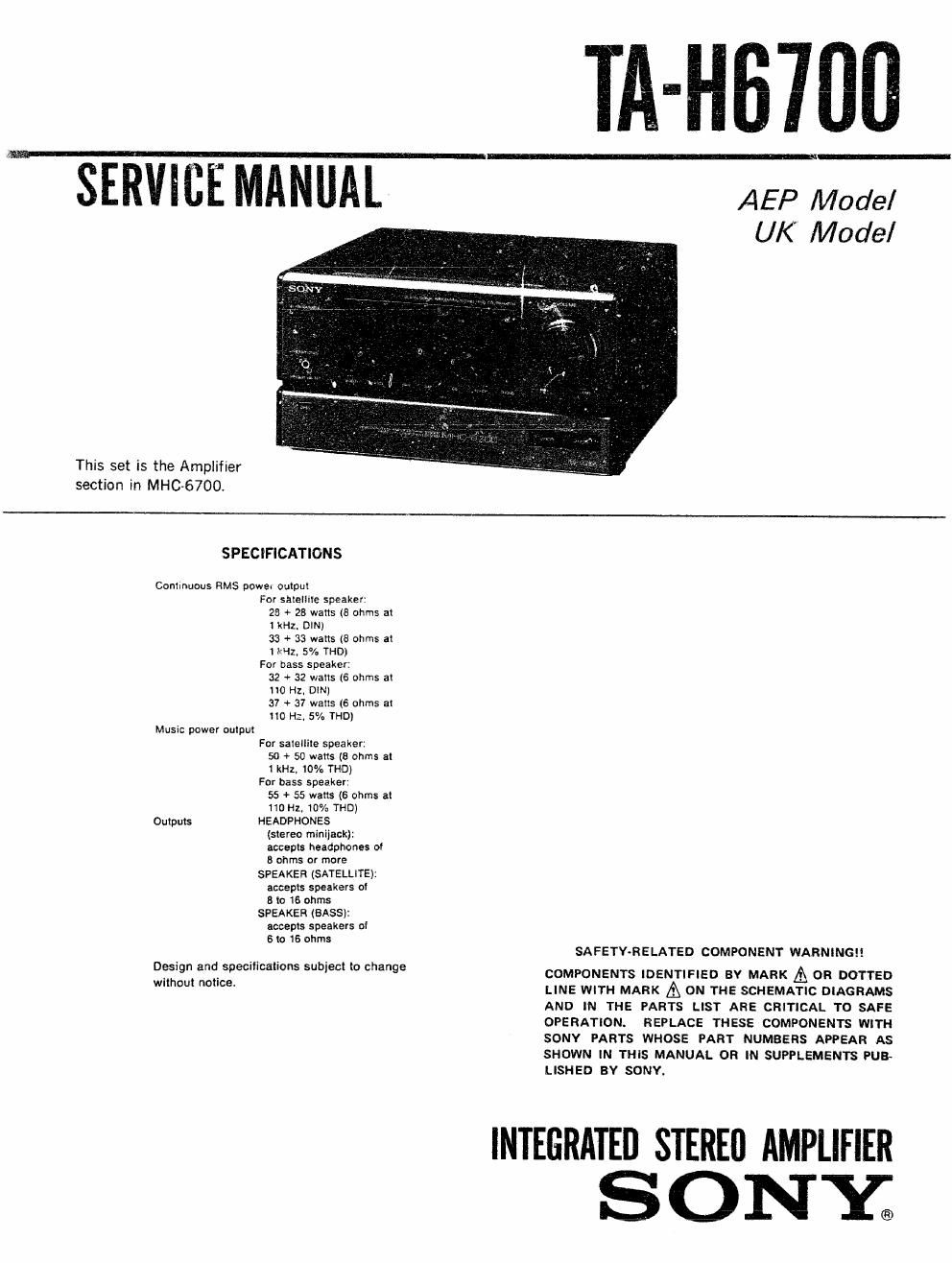
sony ta h 6700 service manual

Extracted text from sony ta h 6700 service manual (Ocr-read)


Page 1

SERVICE MANUAL

This set is the Amplifier
section in MHC-6700.

TA-Hfimfl

AEP Model
UK Model

SPECIFICATIONS

Continucus HMS powe. output
For satellite speaker:
25 + 23 Watts (8 ohms 3
1 kHz. DIN)
33 + 33 watts (3 arms at
I kHz, 5% THD}
For bass speaker:
32 + 32 wans [6 ohms 2!
110 Hz. DIN)
37 + 37 wants (6 ohms at
110 Hz. 5% THD)
Music power oulpux
For satellite speaker:
50 + 50 mans (5 arms at
1 kHz, 10% THD)
For bass speaker
55 + 55 watts (6 ohms at
110Hl, 10% THE!)
Outputs HEADPHONES
(slerea minijack):
accepis headphones 01
8 ohms or more
SPEAKER (SATELLITE):
accepts speakers 01
B I0 16 ohms
SPEAKER (BASS):
accepis speakers of
6 lo 16 ohms

Design and specifications subject to change
without notice.

INTEGRA

SA FETY~R E LATED COMPONENT WARNING

COMPONENTS IDENTIFIED BY MARK A OR DOTTED
LINE WITH MARK A ON THE SCHEMATIC DIAGRAMS
AND IN THE PARTS LIST ARE CRITICAL TO SAFE
OPERATION. REPLACE THESE COMPONENTS WITH
SONY PARTS WHOSE PART NUMBERS APPEAR AS
SHOWN IN THIS MANUAL OR IN SUPPLEMENTS PUB«
LISHED BY SONY.

37mm AMPLIFIER
S O NY®

Page 2

TA-H6700 I

TABLE OF CONTENTS


MODEL IDENTIFICATION
~ Model Number Label - 1- GENERAL
1»1. Parts Identification ............................... 2
SONY MODEL N0, TA~H6700 2- DISASSEMBLV
INTEGRATED STEREO AMPLIFIER 24' Front Panel Aggy """""""

22, Panel Board .................. T
2-3 Back Panel ...................................... 4
2-4. Jack Board, Speaker Board .
2-5. Power Board. DSP Board. T
2-6 Power Transformer

AEP modei : .ac: 220-230V~50/60Hz 3' DIAGRAMS

Italian model : AC: 220-230v~50Hz 3-1 Circuit Boards Location .......................... 6

Gflmny we 55 MHC'5709 3-2, Semiconductor Lead Layouts ..................... 5

AC: 220-230V~50Hz
UK model ; AC: 24ov~5on 3-3. Printed Wiring Boards
- Power/Jack/Volume Section - .................. 8
34. Schematic Diagram
- Power/Jack/Volume Section - ........... V c 11
3-5. Schematic Diagram - DSP Section- .14
3-6. Printed Wiring Board - DSP Section - 17
3-7. Printed Wiring Board - Pane] Section _ .......... 21
3-8i Schematic Diagram - Panel Section - ............ 25
4. EXPLODED VIEWS
4-1. Front Panel Assy ................................ 29
4-2. Chassis Section .............................
5. ELECTRICAL PARTS LIST ..................... 31
SECTION 1
GENERAL

1-1. PARTS IDENTIFICATION

E SYSTEM POWER switchand ,
' STANDBY indicatcir

The indicator remains in as long as the
AC' power cord Is connected to a wail
outlet.

E] HEADPHONES jack (stereo miniiacki

Display window

E VOLUME control 0

[3 VIDEO and AUDIO FUNCTION
selectors @ 0

I Function Indicators 0 0 _.V

[73 WAKE up VOI; sEr' indicator 0

[1'] OPEN mo

This section is extracted from
instruction manuai.