Sony ta fe 600 r service manual

This is the 20 pages manual for sony ta fe 600 r service manual.
Read or download the pdf for free. If you want to contribute, please upload pdfs to audioservicemanuals.wetransfer.com.

Page: 1 / 20
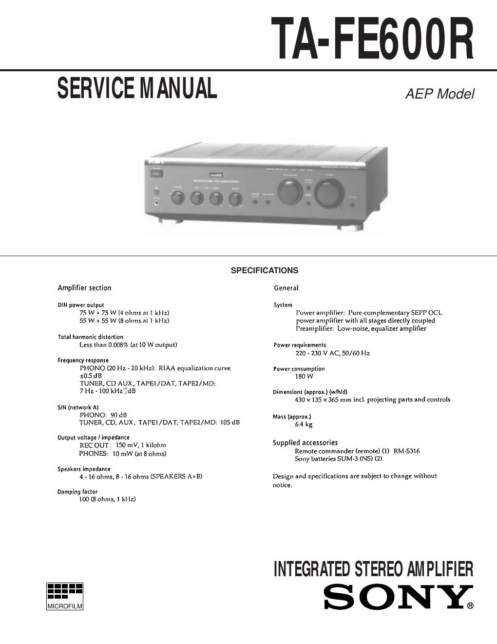
sony ta fe 600 r service manual

Extracted text from sony ta fe 600 r service manual (Ocr-read)


Page 1

TA-FE600R

SERVICE MANUAL

AEP Model

SPECIFICATIONS
Amplifier section General
DIN power output System

75 W + 75 W (4 ohms at I kHz)
55 W + 55 W (8 ohms at] kHz)

total harmonic distortion
Less than 0.008% (at ll) W output)

Frequency response
PHONO (20 Hz - 20 kHz): RlAA equalization curve
:05 dB
TUNER, CD AUX, TAPEl /DAT, TAPEZ/MD:
7 Hz <100 kHszz'dB

SIN (network A)
PHONO: 90 dB
TUNER, CD, AUX, TAPEl/DAT, TAPEZ/MD; 105 dB

Output voltage I impedance
REC OUT: 150 mV,l kilohnt
PHONES: 10 mW (at 8 ohms)

Speakers impedance
4 - 16 ohms, 8 - 16 ohms (SPEAKERS A+B>

Damping lactor
100 (8 ohms, 1 kHz)

MICROFILM

lower amplifier: Pure-complementary SEPP OCL
power amplifier with all stages directly coupled
Preamplifier: Low-noise, equalizer amplifier

Power requirements
220 - 130 V AC, 50/60 Hz

Power consumption
180 W

Dimensions (approxt) (wlhld)
430 x135 x365 mm incl. projecting parts and controls

Mass (approx)
64 kg

Supplied accessories
Remote commander (remote) (l) RM-S316
Sony batteries SUM-3 (N5) (2)

Design and specifications are subject to change without
notice

INTEGRATED STEREO AMPLIFIER

SONY®

Page 2

TABLE OF CONTENTS

1. GENERAL ........................................................ 3
2. ELECTRICAL ADJUSTMENT ....................................... 4
3. DIAGRAMS

3A1. Circuit Boards Location ....................................................... 5
3-2. IC Pin Function

3A3.
3A4.
3A5.
3A6.

' IC902 Input Control LED Driver
(TMP47C IO3N-JP47) .....................
Schematic Diagram 7 Panel Section 7
Printed Wiring Board 7 Panel Section 7
Schematic Diagram 7 Main Section 7
Printed Wiring Board 7 Main Section 7

4. EXPLODED VIEWS

4.1
4.2

5. ELECTRICAL PARTS LIST

. Front Panel Section ............................................................ l9
. Chassis Section ................................................................... 20

SAFETY-RELATED COMPONENT WARNING I!

COMPONENTS IDENTIFIED BY MARK A OR DOTTED LINE
WITH MARK A ON THE SCHEMATIC DIAGRAMS AND IN
THE PARTS LIST ARE CRITICAL TO SAFE OPERATION.
REPLACE THESE COMPONENTS WITH SONY PARTS
WHOSE PART NUMBERS APPEAR AS SHOWN IN THIS
MANUAL OR IN SUPPLEMENTS PUBLISHED BY SONY.

_2_