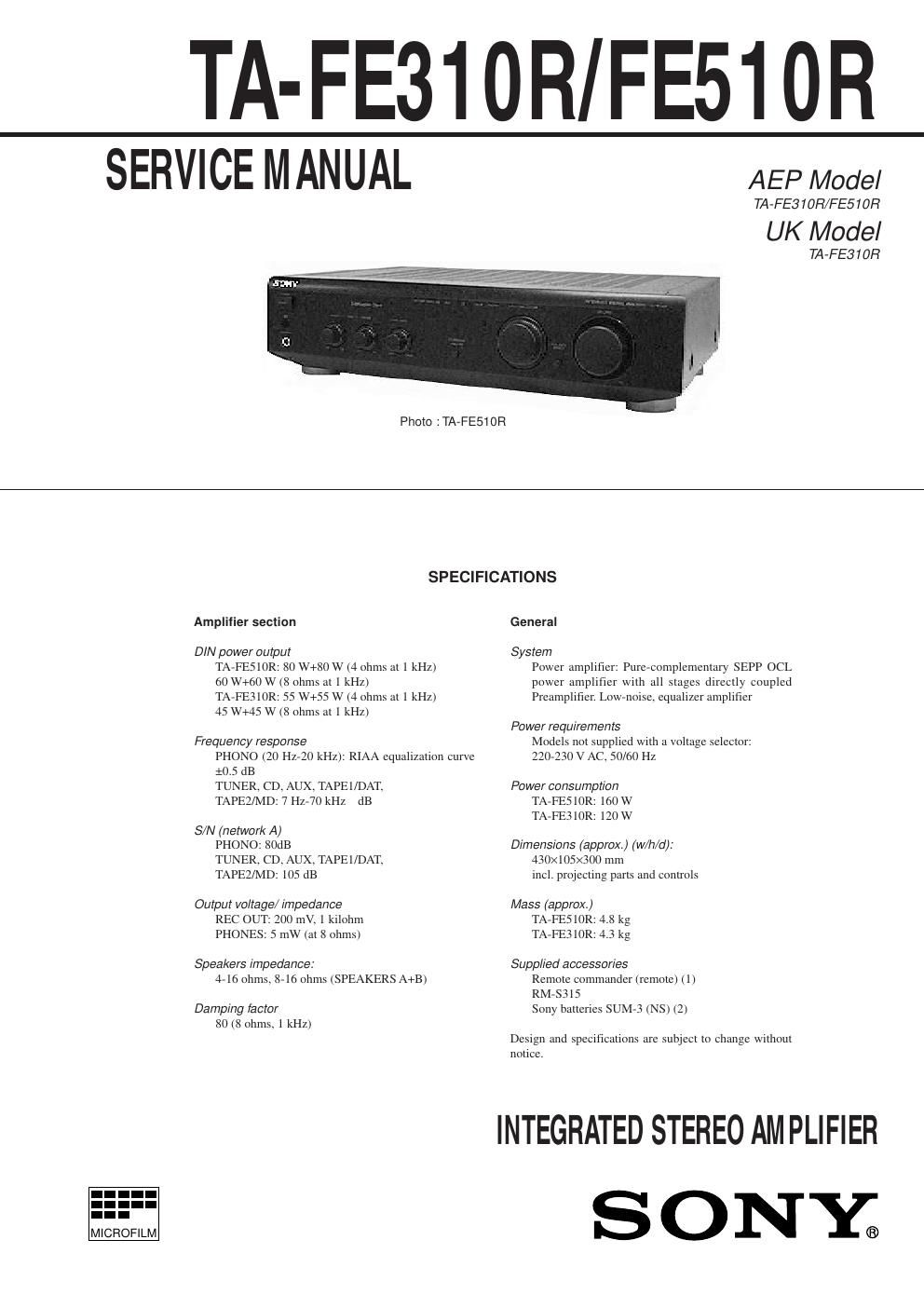
Sony ta fe 310 r service manual
This is the 17 pages manual for sony ta fe 310 r service manual.
Read or download the pdf for free. If you want to contribute, please upload pdfs to audioservicemanuals.wetransfer.com.
Extracted text from sony ta fe 310 r service manual (Ocr-read)
Page 1
Ñ 2 Ñ 1. GENERAL 1-1. Index to Parts and Controls ................................................ 2 2. DIAGRAMS 2-1. Circuit Boards Location ..................................................... 3 2-2. IC Pin Function Description ............................................... 4 2-3. Schematic Diagram Ñ Main Section Ñ ............................ 5 2-4. Printed Wiring Boards Ñ Main Section Ñ ........................ 7 2-5. Schematic Diagram Ñ Panel Section Ñ ............................ 9 2-6. Printed Wiring Boards Ñ Panel Section Ñ ..................... 11 2-7. Schematic Diagram Ñ Power Section Ñ ........................ 13 3. EXPLODED VIEWS ................................................. 15 4. ELECTRICAL PARTS LIST ................................. 17 SAFETY-RELATED COMPONENT WARNING!! COMPONENTS IDENTIFIED BY MARK ! OR DOTTED LINE WITH MARK ! ON THE SCHEMATIC DIAGRAMS AND IN THE PARTS LIST ARE CRITICAL TO SAFE OPERATION. REPLACE THESE COMPONENTS WITH SONY PARTS WHOSE PART NUMBERS APPEAR AS SHOWN IN THIS MANUAL OR IN SUPPLEMENTS PUBLISHED BY SONY. SECTION 1 GENERAL 1-1. INDEX TO PARTS AND CONTROLS Front Panel Rear Panel 1234 5 6 7 !ª !Á 0 9 8 1SYSTEM POWER switch 2BASS control 3TREBLE control 4BALANCE control 5INPUT SELECTOR indicators 6INPUT SELECTOR 7VOLUME control 8PHONES jack 9LOUDNESS switch !¼TAPE 1 MONITOR switch (TA-FE510R only) !ÁSOURCE DIRECT switch !ªEON LINK switch (TA-FE510R only) This section is extracted from instruction manual. TABLE OF CONTENTS
Page 2
SECTION 2 DIAGRAMS 2-1. CIRCUIT BOARDS LOCATION RELAY AC board SIRCS board HP board FUNCTION SW board CONTROL board EON board (FE510R) MAIN board AC board (AEP, Germany) SP board AC SW boardRELAY DC board 2-2. IC PIN FUNCTION DESCRIPTION CONTROL BOARD IC801 TMP47C103N (INPUT CONTROL, LED DRIVE) Pin No. Pin Name I/O Function1 X OUT O System clock. (4 MHz) 2 X IN I System clock. (4 MHz) 3 RESET I RESET input. 4 PMD I MODE select input. 5 VOL+ O Motor drive output (+). 6 VOL Ð O Motor drive output (Ð). 7 SW0 I Rotary switch input (CD). 8 SW1 I Rotary switch input (TUNER). 9 SW2 I Rotary switch input (PHONO). 10 EON I EON signal input. 11 PHONO O PHONO LED drive output. 12 TUNER O TUNER LED drive output. 13 CD O CD LED drive output. 14 GND Ð Ground. 15 AUX O AUX LED drive output. 16 DAT O TAPE ÒZÓ LED drive output. 17 TAPE O TAPE Ò1Ó LED drive output. 18 MON O MONITOR output. 19 PRY O Power relay output. 20 PKY I Power key input. 21 MON I MONITOR input. 22 SIRCS I SIRCS input. 23 MUTE O Muting output. 24 SCE O Chip enable output. 25 SDT O Serial data output. 26 SCK O Serial clock output. 27 STOP I Stop input. 28 +3 V Ð +3 V power supply. Ñ 3 ÑÑ 4 Ñ