Sony ta fb 720r service manual

This is the 26 pages manual for sony ta fb 720r service manual.
Read or download the pdf for free. If you want to contribute, please upload pdfs to audioservicemanuals.wetransfer.com.

Page: 1 / 26
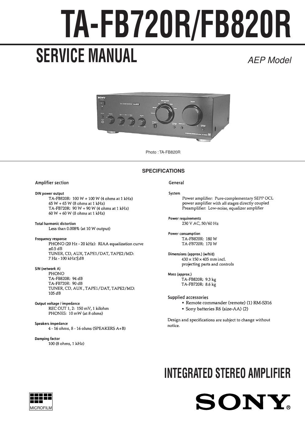
sony ta fb 720r service manual

Extracted text from sony ta fb 720r service manual (Ocr-read)


Page 1

Ð 2 Ð SAFETY-RELATED COMPONENT WARNING !! COMPONENTS IDENTIFIED BY MARK ! OR DOTTED LINE WITH MARK ! ON THE SCHEMATIC DIAGRAMS AND IN THE PARTS LIST ARE CRITICAL TO SAFE OPERATION. REPLACE THESE COMPONENTS WITH SONY PARTS WHOSE PART NUMBERS APPEAR AS SHOWN IN THIS MANUAL OR IN SUPPLEMENTS PUBLISHED BY SONY. TABLE OF CONTENTS 1. GENERAL .......................................................................... 3 2. ELECTRICAL ADJUSTMENT ..................................... 4 3. DIAGRAMS 3-1. Circuit Boards Location ........................................................ 5 3-2. Schematic Diagram Ð Input Section Ð .................................. 7 3-3. Printed Wiring Board Ð Input Section Ð ................................ 9 3-4. Schematic Diagram Ð Main Section Ð ................................ 11 3-5. Printed Wiring Board Ð Main Section Ð .............................. 13 3-6. Schematic Diagram Ð Panel Section Ð ................................ 15 3-7. Printed Wiring Board Ð Panel Section Ð ............................. 17 3-8. Schematic Diagram Ð Power Section Ð ............................... 19 3-9. Printed Wiring Board Ð Power Section Ð ............................ 21 3-10. IC Block Diagrams ............................................................ 23 3-11. IC Pin Function ................................................................. 24 4. EXPLODED VIEW 4-1. Case and Back Panel Section .............................................. 25 4-2. Front Panel Section ............................................................. 26 4-3. Chassis Section ................................................................... 27 5. ELECTRICAL PARTS LIST ........................................ 28

Page 2

Ð 3 Ð Front Panel Descriptions SECTION 1 GENERAL 1PROTECTION indicator 2U (Power) button 3Remote sensor 4TAPE 1/DAT indicator 5TAPE 2/MD indicator 6AUX indicator 7CD indicator 8TUNER indicator 9PHONO indicator 10INPUT SELECTOR knob 11VOLUME knob12SUBSONIC button 13SOURCE DIRECT button and indicator 14LOUDNESS button 15TAPE MONITOR knob 16BALANCE knob 17TREBLE knob 18BASS knob 19SPEAKERS knob 20PHONE jack 21EON LINK button This section is extracted from instr uction manual. 10 3 2 1 9 78 465 11 13 12 14 15 16 17 18 19 20 21