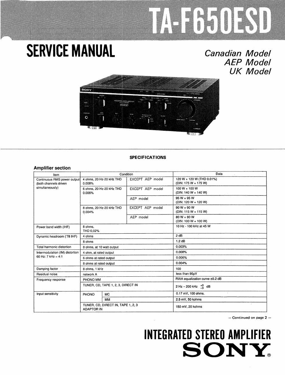
Sony ta f 650 esd service manual
This is the 22 pages manual for sony ta f 650 esd service manual.
Read or download the pdf for free. If you want to contribute, please upload pdfs to audioservicemanuals.wetransfer.com.
Extracted text from sony ta f 650 esd service manual (Ocr-read)
Page 2
TA-F65OESD
Item Condition Data
S/N (network) PHONO MC 77 (0,5mV)
MM 95 (5.0mV)
78 (tHF) TUNER. co. DIRECT lN. TAPE 1. 2. a 108 (150W)
ADAPTOR IN
Output voltage impedance REC OUT I. 2. 3 150 mV, 1 kohm
ADAPTOR OUT
HEADPHONES 25 miliwatts (at 8 ohms)
Accepts tow and highglmpedance headphones,
Tone controls pASS, at 100 Hz :65 dB
(turnover Iraq. 400 Hz)
TREBLE. at 10 kHz :6 dB
(treq. 5 kHz)
SUBSONIC tiller - 6 dB/octave attenuation below 15H:
DA converter section
Item Condition Data
Input sensitivity DIGITAL COAXIAL IN 0.5 Vp»p. 120%, 75 ohms
DIGITAL OPTICAL IN 1. 2 TOSLINK
Output voltage impedance DIGITAL OPTICAL 2 REC OUT TOSLINK
Output voltage DA converter 2 V
General AC outlet
System Preamplifier section: Low-nolse high gain NFB type _ _
equalizer amplifier, passive type direct tone control Canadian m°de' $03wxglgfd.;a:n:rgached.
Power amplifier section: Pure-complementary SEPP s
power amplifier AEP. UK. _
West Germany model
Power requirements
Canadian model: 120v Ac, 5on Dimensions
AEP, West Germany model : 220V AC, 50H: Approx. 430 x150 x 390 mm (w/h/d)
U K model: 240 V AC, 50 Hz (18'l2 X 5% X 153/3 inches)
. Weight
Power consumptlon Approx, 11.8 kg (26 lbs 1 02) net
Canadian model 520 VA
Asp mode. 210 w Design and specifications sublect to change without notice.
UK model 620 W Note
WSS Germany model 330 W This appliance contorms with EEC directive 87/308/EEC
regarding interference suppression,
TABLE OF CONTENTS
Section Title Page Section Title Page
Specificationm-nm- 3. DIAGRAMS
Model Identification - 3-1t 1C Pin Function"
Safety Check-Out ~~~~~ ...............3 3-2. Circuit Boards Location
3-3. Schematic Diagram -AMP Section- -
1. GENERAL 34, Printed Wiring Boards -AMP Section
1-1. Parts Identificationnmv ~~~~~~~~~~~~~~~~ ~ ----- ~~~~~~~~~~~~~~~~ 4 3-5. Schematic Diagram -DAS Section- ------- ~-
3-6t Printed Wiring Boards ~DAS Section- ~~~~~~~ - ~~~~~~~ 23
2. ADJUSTMENTS ............ ............................... ......5
4. EXPLODED VIEWS ....................... ..................... 25
5. ELECTRICAL PARTS LIST ........... ..................... .. 28