Sony ta f 60 int service manual

This is the 12 pages manual for sony ta f 60 int service manual.
Read or download the pdf for free. If you want to contribute, please upload pdfs to audioservicemanuals.wetransfer.com.

Page: 1 / 12
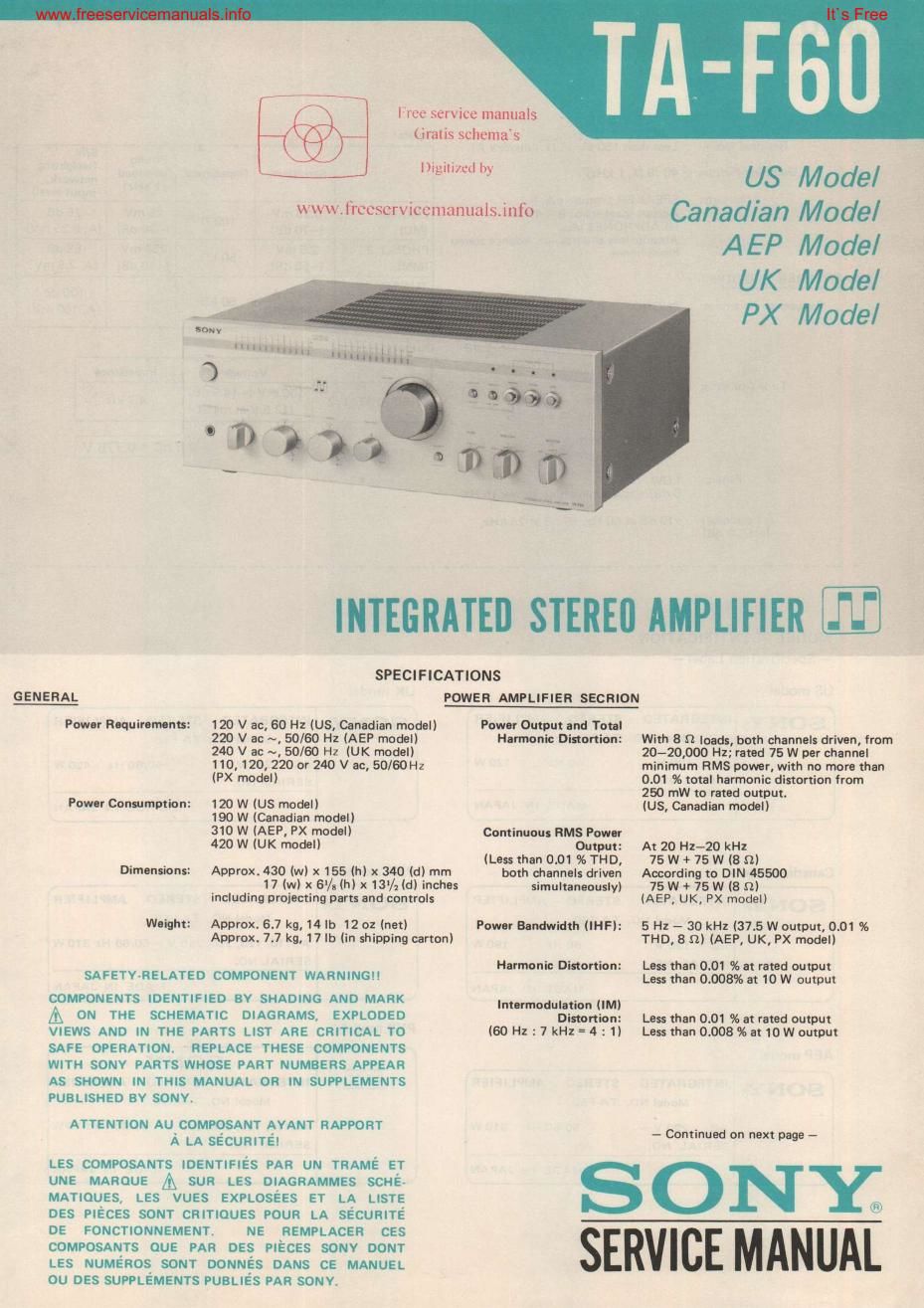
sony ta f 60 int service manual

Extracted text from sony ta f 60 int service manual (Ocr-read)


Page 1

www.frccscrviccmanualsjnfo

INTEGRATED STEREII AMPLIFIER

SPECIFICATIONS

GENERAL POWER AMPLIFIER SECRION

Power Requirements: 120 V ac, 60 Hz (US, Canadian model)

220 V ac ~, 50/60 Hz (AEP model)
240 V ac ~. 50/60 Hz (UK model)

110,120, 220 or 240 V ac, 50/60H2

(PX model)

Power Conumptinn: 120 W IUS model)
190 W (Canadian model)
310 W (AEP, PX model)
420 W (UK model)

Dimensions! Approx.430 (WI x 156 (h) x 340 Id) mm

Iree service manuals
Umlis schemas

17 (w) x 6/, (h) x 131/1 (d) inches
including projecting parts and controls

Weight: Approx. 6.7 kg, 14 lb 12 0: (net)
Approx. 7.7 kg, 17 lb (in shipping carton)

SAFETVJELATED COMPONENT WARNINGI!

COMPONENTS IDENTIFIED 8V SHADING AND MARK
A 0N TNE SCHEMATIC DIAGRAMS, EXPLDDED
VIEWS AND IN THE PARTS LIST ARE CRITICAL T0
SAFE OPERATION. REPLACE THESE COMPONENTS
WITH SONY PARTS WHOSE PART NUMBERS APPEAR
AS SHOWN IN THIS MANUAL OR IN SUPPLEMENTS
PUBLISHED BY SONYL

ATTENTION AU COMPOSANT AYANT RAPPORT
A LA SECURITE!

LES composams IDENTIFlES PAR un TRAME ET
UNE MAROUE A sun LEs DIAGRAMMES scuév
MATIOUES, LEs qus EXPLosEEs ET LA LISTE
DES PIECES sou'r CRITIQUES POUR LA sEcumTE
DE FONCTIONNEMENT. NE REMPLACEH CES
COMPOSANTS ouE PAR DES PIEcEs souv DONT
LEs NUME'Ros sour DouNEs DANS CE MANUEL
ou DEs SUPPLEMENTS PuaLIEs PAR souv.


US Model
Canadian Model
AEP Model

UK Model
PX Model

Power Output and Tnnl
Harmonic Distortion: With 8 fl loads, both channels driven, from

20-20,000 Hz; rated 75 W per channel
minimum RMS pomr, with no more than
0.01 as total harmonic distortion from
250 mW to rated output.

(Us, Canadian model)

Continuous RMS Power

Output: At 20 Hz-zo kHz

(Less than 0.01%THD, 76W+ 75W (8 :1)
both channels driven According to DIN 45500
simultaneously) 75 W + 75 W [8 n)

(AEP, UK, PX model)

Power Bandwidth (IHF): 5 Hz v 30 kHz (37.5 W output, 0.01 96

THD, 8 n) (AEP, UK, Px model)

Harmonic Dinortian: Less than 0.01 as at rated output

Less than 0.008% at 10 W output

lntermodulatinn (IMI

Distortion: Less than 0.01 96 at rated output

(60 Hz :7 kHz-4 : 1) Less than 0.008%at 10W output

- Continued on next page -

SERVICE MANUAL

Page 2

rvi emanualsinfo
TRY? i

Residual Noise:
Damping Factor:

Outputs:

PREAMPLIFIER SECTION

Frequency Response:

Tone Controls:

F itt-rs:

Loudness:
Int. 30 dB)

Less than 150 AV (8 12, network A)
40 I8 9, 1 kHz)

SPEAKER terminals A, 8

Accept speakers of 8 - 16 n
HEADPHONES iack

Accepts low and high-impedance stereo
headphones

PHONO: RIAA equalization curve

:02 dB

TUNER

AUX ) 3 - 70.000 Hz*° as
TAPE 1,2 1

BASS
:10 dB at 60 Hz
(turnover frequency 300 Hz)
TREBLE
110 dB at 25 kHz
(turnover frequency 5 kHz)

LOW
6 dB/octave attenuation below 15 Hz

+10dE at 60 Hz. +6 :13 at 25 kHz

Inputs:
SIN
Phono . .
Sensitivity ImPOdance overload IWBIIIII'IQ
(1 kHz) '."°' -
Input level)
PHONO 0.25 mV 1m n 25 mV 75 dB
(MC) (-70 dB) (-30 dB) (A, 0.25 mVI
PHONO 2 2.5 NW 50 kt) 250 mV 88 dB
(MM) (-50 dB) (-10 dB) (A, 2.5 mV)
zldliER 150 mV 50 k0 100 dB
TAPE 12 (-14.5 dB) IA, 150 mV)
Outputs:
Volt-go Impedance
150 mV (-14.5 dB)
. n
REC OUT 1'2 (13.5Vat max.) 47"
.775 V

MODEL IDENTIFICATION
- Specifialtion Label -

US model

UK modal

SONY® INTEG RATED

AC

STEREO AMPLIFIER
Model No. TA-FSO

120 V 60 Hz 120W

SERIAL NO.

MADE IN JAPAN

SONan INTEGRATED

STEREO AMPLIFIER
Modal Nor TAVFGO

AC 240 V ~
SERIAL NO,

50/50 Hz 420 W

MADE IN JAPAN

Canadian model

PX1 model

SONY® INTEGRATED

AC

STEREO AMPLIFIER
Model No. TAaFSO

120 V 50 H1 190 W

SERIAL NO.

MADE IN JAPAN

SONY® INTEGRATED

STEREO AMPLIFIER
Model NO. TAEFSO

AC1"), 120, 220, 240 V ~ 50/60 HZ 310W
SERIAL NO.

MADE IN JAPAN

PX2 model
AEP model
SONYe
SONYQ INTEGRATED STEREO AMPLIFIER A500 INTEGRATED STEREO AMPLIFIER

AC

Model NOI TA-FSO

220 V ~ 50/50 Hz 310W

SERIAL NO.

MADE IN JAPAN

Model No. TAvFEO

ACIID, 120, 220. 240 V ~ 50/60 Hz 310W
SERIAL NO.

MADE IN JAPAN

w. firf -7 a

SERVICING

1. PULSE POWER SUPPLY BOARD REPAIRING
This set has a pulse power-supply circuit which
is quite different from a conventional power-
supply circuit. The pulse power supply directly
retifies and smooths the ac input power to pro-
duce the higher dc voltages required in the power
supply circuit, When servicing this set, note the
following.

a) To prevent unwanted radiation due to pulse
signals in the pulse power-supply circuit, the
pulse power-supply board is shielded by the
aluminum diccast box.

b) The negative circuit of the secondary rectifier
in the pulse powersupply circuit is grounded
by screws in the aluminum diecast box. When
checking the pulse powersupply board out
of the box, use a jumperwire and a cardboard
insulator as shown on the right.

'I'A-FbO TA-F60

NOTE

pulse power-supply


alumin um
disses! box

iu mper
wire
chassis

cardboard
insulator

-mv,toaor.-..,-.-.o.-0-.-. ..-.-0-,-.-.-I.-.o.-.---.-.o.-.-.-»-.-,-.-.-.-.-.-.---.-.-.-.

2. Take care that electrolytic capacitor C414 which
is used after the rectification of ac power soure
voltage is charged even if the POWER switch is
turned off. Be sure to use a resistor of at least
several hundred ohms to discharge the capacitor,
Direct discharge by means of lead is dangerous.

3. INVERTER CIRCUIT TRANSISTOR REPLACEMENT (0903-906)

When replacing 0903-Q906 in the pulse power-
supply circuit, use those which have the same hFE
rank and color code.

US, Canadian model

AEP, UK, PX mod-I

hFE rank 0 hFE rank
09037906 ZSCI968D»0 - - < 0 Color Code Q903, 904 MN8301C - -- 0
El 1] black
198613 (33;!)
I] D @ red 0 ~ Color Code

black
MN8301C blue )

green
0 D red
Color Code
black
blue
green

Its Free

__4E