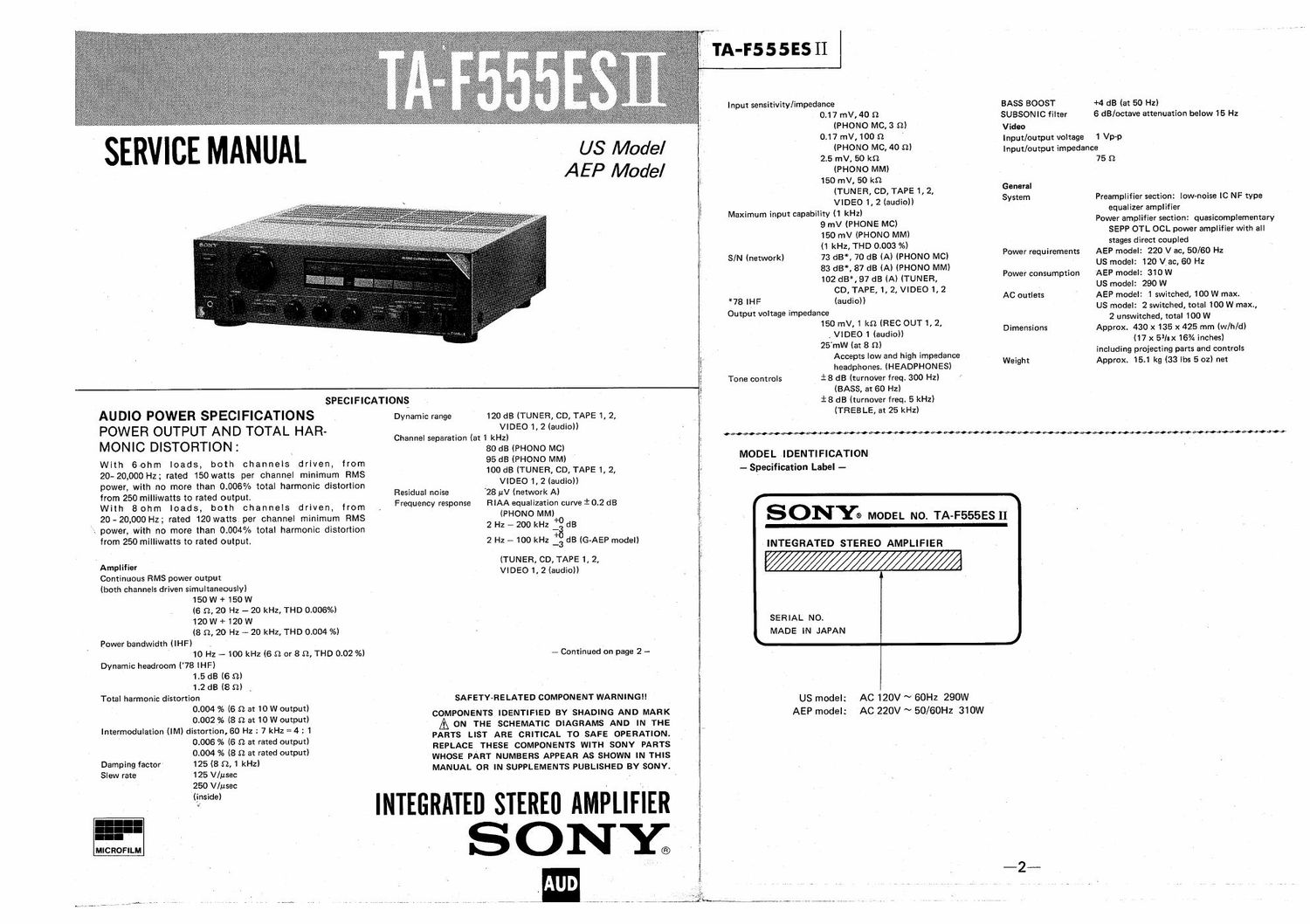
Sony ta f 555esii service manual
This is the 24 pages manual for sony ta f 555esii service manual.
Read or download the pdf for free. If you want to contribute, please upload pdfs to audioservicemanuals.wetransfer.com.
Extracted text from sony ta f 555esii service manual (Ocr-read)
Page 1
US Model
A E P Model
SPECIFICATIONS
AUDIO POWER SPECIFICATIONS
POWER OUTPUT AND TOTAL HAR-
MONIC DISTOFITION:
With 60hm loads, both channels driven, from
20-20,000 Hz; rated 150watts per channel minimum RMS
power, with no more than 0.006% total harmonic distortion
from 250 milliwatts to rated output.
With 8 ohm loads, both channels driven, from
20-20,000 Hz; rated 120 watts per channel minimum RMS
power, with no more than 0.004% total harmonic distortion
from 250 milliwatts to rated output.
Amplifier
Continuous RMS power output
(both channels driven simultaneously)
150 W + 150 W
(6 Q, 20 Hz - 20 kHz, THD 0.006%)
120 W + 120 W
(8 S7,, 20 Hz 4 20 kHz, THD 0.004 %)
Power bandwidth (IHF)
10 Hz - 100 kHz (6 S7. or 8 SI. THD 0.02 %)
Dynamic headroom ('78 IHF)
1.5 dB (6 n)
1.2 dB (8 D) \
Total harmonic distortion
0.004 % (6 0 at 10 W output)
0.002 % (8 Q at 10 W output)
Intermodulation (IM) distortion, 60 Hz : 7 kHz = 4 g 1
0.006 % (6 n at rated output)
0.004 % (8 n at rated output)
125 (8 9.1 kHz)
125 V/usec
250 V/usec
(inside)
Damping factor
Slew rate
MICROFILM
Dynamic range 120 dB (TUNER, CD, TAPE 1, 2,
VIDEO 1, 2 (audio))
Channel separation (at 1 kHz)
80 dB IPHONO MC)
95 dB (PHONO MM)
100 dB (TUNER, CD, TAPE 1, 2,
, VIDEO 1, 2 (audio))
28 uV (network A)
RIAA equalization curve i 0.2 dB
(PHONO MM)
2 Hz - 200 kHz :8 dB
2 Hz a 100 kHz _3 dB (G-AEP model)
(TUNER, CD, TAPE 1, 2,
VIDEO 1, 2 (audio))
Residual noise
Frequency response
- Continued on page 2 -
SAFETY-RELATED COMPONENT WARNING
COMPONENTS IDENTIFIED BY SHADING AND MARK
A ON THE SCHEMATIC DIAGRAMS AND IN THE
PARTS LIST ARE CRITICAL T0 SAFE OPERATION.
REPLACE THESE COMPONENTS WITH SONY PARTS
WHOSE PART NUMBERS APPEAR AS SHOWN IN THIS
MANUAL OR IN SUPPLEMENTS PUBLISHED BY SONY.
INTEGRATED STEREO AMPLIFIER
S ON-Y;
TA-F555ES 11
Input sensitivity/impedance
BASS BOOST
0.17 mV, 40 D SUBSONIC fiIter
(PHONO MC, 3 a) Video
0-17 mV.100 9 Input/output voltage
(PHONO MC, 40 n)
2.5 mV, so m
(PHONO MM)
150 mV, so to
(TUNER, co, TAPE 1, 2, mm"
System
VIDEO 1, 2 (audio))
Maximum input capability (1 kHz)
S/N (network)
*781HF
9 mV (PHONE Mc)
150 mV (PHONO MM)
(1 kHz,THD 0.003 as)
73 dB, 70 dB (A) (PHONO Mc)
83 dB, 87 dB (A) (PHONO MM)
102 (55*, 97 dB (A) (TUNEFI,
CD,TAPE, 1, 2, VIDEO 1, 2
Power requirements
Power consumption
Output voltage impedance
Tone controls
(audio)) AC outlets
150 mV,1 kn (REC OUT1, 2, Dimensions
, VIDEO 1 (audio))
25mW (at 8 n)
Accepts low and high impedance Weight
headphones. (HEADPHONES)
i 8 dB (turnover freq. 300 HZ)
(BASS, at 60 Hz)
i 8 dB (turnover freq. 5 kHz)
(THEBLE, at 25 kHz)
.,
MODEL IDENTIFICATION
- Specification Label -
SONYa moon N0. TA-F555ES II
INTEGRATED STEREO AMPLIFIER
SERIAL NO.
MADE IN JAPAN
US model:
AEP model:
AC 120V ~ 60Hz 290W
AC 220V ~ 50/60HZ 310W
+4 dB (at 50 Hz)
6 dB/octave attenuation below 15 Hz
1 Via-p
Input/output impedance
759
Preamplifier section: low-noise l0 NF type
equalizer amplifier
Power amplifier section: quasicomplementary
SEPP OTL OCL power amplifier with all
stages direct coupled
AEP model: 220 V ac, 50/60 Hz
US model: 120 V ac, 60 Hz
AEP model: 310 W
US model: 290 W
AEP model: 1 switched, 100 W max.
US model: 2 switched, total 100 W max.,
2 unswitehed, total 100 W
Approx. 430 x 135 x 425 mm (w/h/d)
(17 x 5qu 16% inches)
including projecting parts and controls
Approx. 15.1 kg (33 lbs 5 02) net
Page 2
SAFETY CHECK-OUT (US Model)
After correcting the original service problem,
perform the following safety check before releasing
the set to the customer:
Check the antenna terminals, metal trim, metallized
knobs, screws, and all other exposed metal parts for
AC leakage. Check leakage as described below.
LEAKAGE TEST
The AC leakage from any exposed metal part to
earth ground and from all exposed metal parts to any
exposed metal part having a return to chassis, must
not exceed 0.5 mA (500 microampers). Leakage
current can be measured by any one of three
methods.
1. A commercial leakage tester, such as the
Simpson 229 or RCA WT-540A. Follow the
manufacturers instructions to 'use these instru-
ments.
2. A battery-operated AC milliammeter. The Data
Precision 245 digital multimeter is suitable for
this job.
m-rsssasn TA-F555ESII
3. Measuring the voltage drop across a resistor by
means of a VOM or battery~operated AC volt-
meter. The limit indication is 0.75 V, so
analog meters must have an accurate low-
voltage scale. The Simpson 250 and Sanwa
SH-63Trd are examples of a passive VOM that
is suitable. Nearly all battery operated digital
multimeters that have a 2V AC range are
suitable. (See Fig. A) ,
To Exposed Metal
Parts on Set
A C
/ voltmeter
(0. 75 V)
0.15uF [I gum
1:- Earlh Ground
Fig. A. Using an AC voltmeter to check AC leakage.
SECTION 1
1-1. FEATURES
A.C.T. (AUDIO CURRENT TRANSFER) TECHNOLOGY
With A.C.T. technology, which reduces interference and
noise as low as possible, the 4 signals of right and left
channels of the preamp and power amp sections are
separated, obtaining the best performance at the nor-
mal listening level. (In the TA-F555ESII, the exclusively
developed audio super Hi-fT IC is employed.)
SUPER LEGATO LINEAR POWER AMPLIFIER STAGE
The operation of the power amplifier stage is stable
without any observable distortion up through the higher
frequencies. Because of its very low switching distor-
tion, the output waveform is smooth.
POWERFUL POWER SUPPLY
Powerful transformers of 250 VA and 350 VA are respec»
tively used in the power supply sections of the
TA-F444ESII and TA-F555ESII to obtain rich sound. In
addition, use of the ES filter together with the newly
developed large chemical capacitor eliminates the
power interference.
SELECTED AUDIO PARTS
A large heatsink and high-rigidity chassis are used to
prevent thermal modulation distortion and vibration
distortion, respectively. LC-OFC (Linear Crystal Oxion-
free Copper) leads are used for internal wiring and
speaker output coil. In addition, other audio parts are
selected by frequent sound monitoring.
_3_
OUTLINE
VARIOUS VIDEO OPERATIONS
This amplifier is equipped with 2 pairs of video jacks
(one pair for playback/recording and one for playback)
to allow you to perform various video operations.
SPEAKER PROTECTION CIRCUIT
When a short circuit or DC component is detected at the
speaker outputs, the power/standby indicator blinks in
red and the built-in speaker protection circuit functions
to protect the speakers.
MUTING CIRCUIT
When the power is supplied, the power/standby in-
dicator blinks in red and the muting circuit functions un-
til the amplifier operation becomes stable.
CARTRIDGE SELECTOR
The high-gain equalizer amplifier stage accepts both
MM (Moving-Magnet) and MC (Moving-Coil) cartridges.
AUDIO REC OUT SELECTOR SWITCH
With the AUDIO REC OUT SELECTOR switch, you can
select the sound source to be recorded while listening
to another audio source. This switch is also used to
select tape (audio and video) dubbing and editing mode.
i
l
l
i
l
1-2. FUNCTION OF CONTROLS
ID .
4 FUNCTION
ATTENUATOFI
BASS/TREE LE
BASS BOOST CARTRIDGE LOAD
AUDIO REC OUT SELECTOR
SPEAKERS SUBSONIC
HEADPHONES
BALANCE
if???" ill? i
i / l V, O O O 0
mm 3""; I :Ztsfow'ni' minim? © (03] © 0 a e a L o
o o . as
await.-. 0000
b . © © co m...
I. © © (3 [a]