Sony ta f 5000 service manual

This is the 18 pages manual for sony ta f 5000 service manual.
Read or download the pdf for free. If you want to contribute, please upload pdfs to audioservicemanuals.wetransfer.com.

Page: 1 / 18
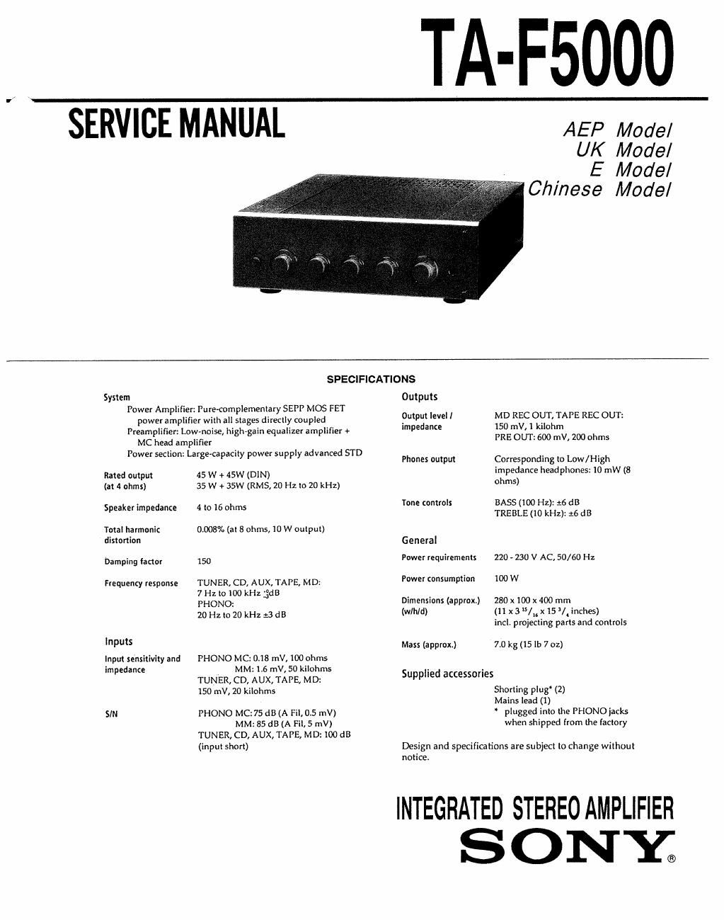
sony ta f 5000 service manual

Extracted text from sony ta f 5000 service manual (Ocr-read)


Page 1

TA-F5000

SERVICE MANUAL

AEP Model
UK Model

E Model
Chinese Model

System

MC head amplifier

Rated output
(at 4 ohms)

SPECIFICATIONS
Outputs
Power Amplifier: Pure-complementary SEPP MOS FET
power amplifier with all stages directly coupled Pull? IVE MD REC OlITliiTAPE REC OUT:
Preamplifier: Low-noise, high-gain equalizer amplifier 4» Impedance IE?E%I}E::I)3 n'TV, 200 ohms
' : - I TD
Power section Large capacrty power supp y advanced 5 Phones 0mm Corresponding 0 Low/High
45 w + 45w (DIN) impedance headphones: 10 mW (8
35 w + 35w (RM5, 20 Hz to 20 kHz) ohms)
Tone controls BASS (100 Hz): :6 dB

Speaker impedance

Total harmonic
distortion

Damping factor

Frequency response

Inputs

Input sensitivity and
impedance

SIN

4 to 16 ohms

0.008% (at 8 ohms, 10 W output)

150

TUNER, CD, AUX, TAPE, MD:
7 Hz to 100 kHz de3

PHONO:

20 Hz to 20 kHz :3 dB

PHONO MC:0r18 mV, 100 ohms

MM: 1.6 mV, 50 kilohms
TUNER, CD, AUX, TAPE, MD:
150 mV, 20 kilohms

PHONO MC: 75 dB (A Fil. 0.5 mV)

MM: 85 dB (A Fil, 5 mV)
TUNER, CD, AUX, TAPE, MD: 100 dB
(input short)

TREBLE (10 kHz): :6 dB
General
Power requirements 220 - 230 V AC, 50/60 Hz
Power consumption 100 W
Dimensions (approx) 280 x100 x 400 mm
(wlhld) (ll x35/x15/inches)

incl, projecting parts and controls

Mass (approx) 7.0 kg (15 lb 7 oz)

Supplied accessories

shorting plug (2)

Mains lead (1)

' plugged into the PI-lONOjacks
when shipped from lhe factory

Design and specifications are subject to change without
notice.

INTEGRATED STEREO AMPLIFIER

SONE

Page 2

TABLE OF CONTENTS

Specification ........................................................ . ..... . .1

1. GENERAL ~~~~~~~~~~~~~~~~

2. ELECTRICAL ADJUSTMENTS~

3

3. DIAGRAMS
3-1. Circuit Boards Location-
3-2. Printed Wiring Boards -- 8
3.3. Schematic Diagram .......................................... 13
4. EXPLODED VIEWS
4-1, Front Panel Section - 19
4-2. Chassis Section ~~~~~~~ 20
5' ELECTRICAL PARTS LIST ..................... ............ 21

Flexible Circuit Board Repairing

0 Keep the temperature of the soldering iron around
270°C during repairing.

0 Do not touch the soldering iron on the same conduc.
tor of the circuit board (within 3 times).

0 Be careful not to apply force on the conductor when
soldering or unsoldering.

Notes on chip component replacement

0 Never reuse a disconnected chip component.
0 Notice that the minus side of a tantalmn capacitor
may be damaged by heat.

SA FETY-RELATED COMPONENT WARNING"

COMPONENTS IDENTIFIED BV MARK A OR DOTTED
LINE WITH MARK A ON THE SCHEMATIC DIAGRAMS
AND IN THE PARTS LIST ARE CRITICAL TO SAFE
OPERATION. REPLACE THESE COMPONENTS WITH
SONY PARTS WHOSE PART NUMBERS APPEAR AS
SHOWN IN THIS MANUAL OR IN SUPPLEMENTS PUB-
LISHED BY SONY.