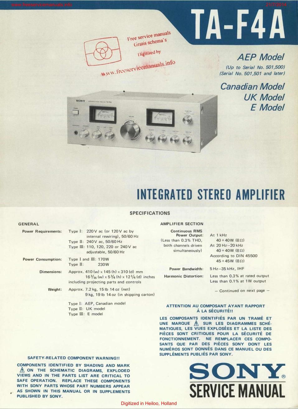
Sony ta f 4a int service manual
This is the 12 pages manual for sony ta f 4a int service manual.
Read or download the pdf for free. If you want to contribute, please upload pdfs to audioservicemanuals.wetransfer.com.
Extracted text from sony ta f 4a int service manual (Ocr-read)
Page 1
Canadian Model
INTEGRATED STEREU AMPLIFIER
SPECIFICATIONS
GENERAL
Power Requiraments: Type I: 220V ac (or 120V ac by
internal rewiring), 50/60 Hz
Type II: 240V ac, 50/60 Hz
Type III: 110,120, 220 or 240V an
adjustable, 50/60 Hz
Power Consumption: Type I and III: 170W
Type [12 230W
Dimensions: Approx 410 (w) x 145 In) x 310 Id) mm
163/151w) x 53/4 (h) x 121/4 Id) inches
including projecting parts and controls
Weighl: Approx. 7.2 kg, 15|b 1402 (net)
9kg, IQIb 1402 (in shipping cartonI
Type I: AEP, Canadian model
Type II: UK model
Type 111: E model
SAFETV-RELATED COMPONENT WARNING
COMPONENTS IDENTIFIED BV SHADING AND MARK
A ON THE SCHEMATIC DIAGRAMS, EXPLOOED
VIEWS AND IN THE PARTS LIST ARE CRITICAL TO
SAFE OPERATION. REPLACE THESE COMPONENTS
WITH SONY PARTS WHOSE PART NUMBERS APPEAR
AS SHOWN IN THIS MANUAL OR IN SUPPLEMENTS
PUBLISHED BY SONY.
AMPLIFIER SECTION
Continuous RMS
Power Output: At 1 kHz
(Less than 0.3% THD, 40+4DW (80)
both channels driven At 20 Hz-ZO kHz
simultaneously) 40+40W (Sn)
According to DIN 45500
45 +45W (851)
Power Bandwidth: 5Hz-35 kHz, IHF
Harmonic Distortion: Less than 0.3% at rated output
Less than 0.1% at 1W output
- Continued on next page A
ATTENTION AU COMPOSANT AYANT RAPPORT
A LA SECURITEII
LES COMPOSANTS IDENTIFIES PAR UN TRAME ET
UNE MARDUE sun LEs DIAGRAMMES SCHE-
MATIQUES, LES VUEs EXPLosEEs ET LA LISTE DES
PIECES som cnmouEs POUR LA sEcunnE DE
FONCTIONNEMENT. NE REMPLAcEn CES com-o-
smns QUE PAR DES PIECES souv DONT LEs
NUMEnos som DoNNEs DANS CE MANUEL ou nEs
SUPPLEMENTS PUBLIEs PAR souv.
SONY;
AEP Model
(Up to Serial No. 507,500)
(Serial No. 501,501 and later}
UK Model
E Model
SERVICE MANUAL
Digitized in Heiloo, Holland
Page 2
.freeserviceman als.info ' ' ' ' " 21/7/2014
lntevmodulation Outputs:
(IMI Distortion: Less than 03% at rated output V
(60 H217 kHz =4:1I Less than 031% at 1W output Output leval Impatience
Froquenw Response: PHONO FIIAA equalization curve 10.3 dB REC OUT l 150 "'V 4.7 kn
TUNER .. (-14.5dB)
Aux 3 a 17 mV
TAPE 1, 5Hzi100 kHz :osaa REC/PB _ 32 k
, TAPE 2 _ (33:13)
(REC/PB) V HEADPHONES Accepts low and high impedance headphones
Residual Noise: Less than aoouv (an, Network A) SPEAKER Amp speake's °f 8-16
I Damping Factor: 35 (an, 1 kHz) Tone Controls: BASS :IOdB at 60Hz (turnover
1 Inputs: frequency 300 Hz)
TREBLE =10d8 at 25 kHz (turnover
I Maximum SIN frequency 5kHzl
input . l
Sensitivity Impedanw upahility Inlimtrlcfl Filters: LOW BdBloct below 15H:
l ($24", input lave}, HIGH GdB/oct above 9 kHz
:
i 25 mV 150 mV BOdB
PHONO (-SUdBI 5° "9 (-14.5dB) (A, 2.5 mVI
TUNER
AUX
150 mV 100dB
TAPE 1 50 kn
TAPE 2 (~14V5dBI (A. 150mv)
.t (REC/PEI
SECTION 1
OUTLIN E
1-1. SERVICING NOTE
When replacing a knob ( SPEAKERS / TREBLE/ l
BASS/BALANCE/FlLTER/TAPE COPY/MONITOR/
FUNCTION), prepare a knob cap (4-854-266-00) and
\ /f) If necessary, widen the slit.
a knob mold (478547267700).
Installation of the knob 15 as follows.
mark Knob Mark Position
\l\(0 SZEEA KERS $0 I
T BL E - (
O BASS - I 0
BALANCE Center
/ FIL TER OFF
TAPE COPY SOURCE
MON! TOR SOURCE
FUNCTION Aux
I 3/]! \
0 Turn. mark
\ 0 Coincide ® with the mark
and install the krmb cap.
0
(/ knnb mp
I knob mold Part No. Description
I
I X4854~21371 Knob Ass'y
1 including;
I 4-854726600 Cap. knob
4-854-26700 Mold, knob
V 2 _
Digitized in Heiloo, Holland