Sony ta f 450esd int service manual

This is the 18 pages manual for sony ta f 450esd int service manual.
Read or download the pdf for free. If you want to contribute, please upload pdfs to audioservicemanuals.wetransfer.com.

Page: 1 / 18
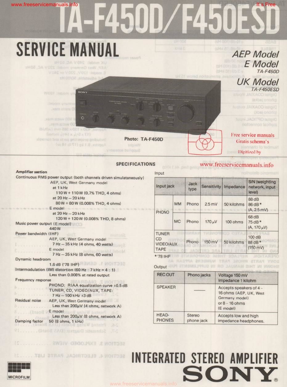
sony ta f 450esd int service manual

Extracted text from sony ta f 450esd int service manual (Ocr-read)


Page 2

memossoro


Tone controls General
, . - x: , S em
. tom , ' I 5
BASS :10 dB (100 Hzl 500 Hz
TREBLE :10 dB (15 kHz) 3 kHz

Loudness (Attenuation 30 GB)
+ 6 dB (100 Hz)
4» 3 dB (10 kHz)

Subsonic tiller GdB/octave, attenuation below 15 Hz

Convener section

Its Free

Preamplifier: Low-noise, high~gain equalizer
amplifier

Power amplifier: Purecomplementary SEPP
OCL power amplifier with all stages directly
coupled

Power requirements

UK model: 240 V Ac, 50 Hz
AEP, West Germany model: 220V AC, 50 Hz
E model: I20V, 220V or 240V

AC adiusteble, 50/60 Hz

Power consumption

Number 0t channels
2 (stereo)
Frequency response

5 Hz - 20 kHz, :03 dB
(Input digital signal sampling freq. 44.1 kHz)

Harmonic distortion
Less than 0.003

"/9 at I kHl

(Input digital signal sampling freq. 44.1 kHz)
Dynamic range More than 107 dB
(Input digital signal sampling freq. 44.1 kHz)

Weight

UK model: 440W

Digital COAXIAL inputs Input level Impedance AEP. West Germany model: 180W

(phono jacks) 0.5 Vp-p 75 ohms E model: 205W

Digital COAXIAL output Output level Impedance AC outlet: A1EP, UKI, West Goeormany model:

(phono jack) 0.5 Vpp 75 ohms E mum~ChNI 1 watts max.

Digital OPTICAL input Input level 2 "pinned, total 100 wan; maxi

(optical COHHGCIOI) 18 dBm _ 1 unswitclled, 100 watts max.
Wavelength Dimensions Approx. 430 x 130 x 365 mm (w/h/dl
660 nm (17 x 51/. x143/I inches)

Including projecting parts and controls
Approx. 8.1 kg (17 lb 14oz)

Supplied accessory

Optical cable (I)

'01-!ioooo-¢oooworoo-dOdowo-lioaOI:o-dol'OI'OIOM00-4w-n-anrutOdom-orthotaoivOUOJO-OO0OJOlofloao

SAFETY-RELATED COMPONENT WARNINGI!

COMPONENTS IDENTIFIED BY MARK A 0R DOTTED
LINE WITH MARK & ON THE SCHEMATIC DIAGRAMS
AND IN THE PARTS LIST ARE CRITICAL T0 SAFE
OPERATION. REPLACE THESE COMPONENTS WITH
SONY PARTS WHOSE PART NUMBERS APPEAR AS
SHOWN IN THIS MANUAL OR IN SUPPLEMENTS PUB-

LISHED BY SONY.

CONTENTS
Section Title Page
Specifications ............................. 1
Model Identification ........................ 3

SECTION 1. GENERAL
Location and Function of Controls ........... 3

SECTION 2. DIAGRAMS

2-1. Semiconductor Lead Layouts .......... 4
2~2. Circuit Boards Location ............... 4
IC Block Diagram ...................
2-3. BLOCK DIAGRAM .................. 6
2-4. Printed Wiring Boards (MAIN Board) ..... 8
2-5. Schematic Diagram (MAIN Board) ...... 13
2-6. Printed Wiring Boards (DAS Board) ..... 16
2-7. Schematic Diagram (DAS Board) ....... 19
SECTION 3. EXPLODED VIEWS ............ 21
SECTION 4. ELECTRICAL PARTS LIST ...... 25