Sony ta f 45 int service manual

This is the 12 pages manual for sony ta f 45 int service manual.
Read or download the pdf for free. If you want to contribute, please upload pdfs to audioservicemanuals.wetransfer.com.

Page: 1 / 12
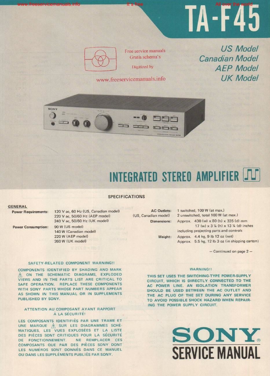
sony ta f 45 int service manual

Extracted text from sony ta f 45 int service manual (Ocr-read)


Page 1

..

www.freescrviccmanuals.info

Free service manuals
Gratis schemas

US Mode/
Canadian Model

Digitized by A EP Model

UK Model

INTEGRATED STEREII AMPLIFIER .I'U'

SPECIFICATIONS

GENERAL
Power Requirements: 120 V ac, 60 Hz (US, Canadian mode
220 V ac, 50/60 Hz (AEP model!
240 v ac, 50/60 Hz (UK model)
Power Consumption: 90 W (US model)
140 W (Canadian modelI
220 W (AEP model)
260W IUK modeII

SAFETY-RELATED COMPONENT WARNINGI!

COMPONENTS IDENTIFIED BY SHADING AND MARK
A ON THE SCHEMATIC DIAGRAMS, EXPLODED
VIEWS AND IN THE PARTS LIST ARE CRITICAL TO
SAFE OPERATION. REPLACE THESE COMPONENTS
WITH SONV PARTS WHOSE PART NUMBERS APPEAR
AS SHOWN IN THIS MANUAL OR IN SUPPLEMENTS
PUBLISHED 8V SONV

ATTENTION AU COMPOSANT AYANT RAPPORT
A LA SECURITE!

LES COMPOSANTS IDENTIFIES PAR UNE TRAME ET
UNE MAROUE A sun LES DIAGRAMMES SCHE-
MATIOUES, LES VUES EXPLOSEES ET LA LISTE
DES PIECES SONT CRITIQUES POUR LA SECURITE
DE FDNCTIONNEMENT. NE REMPLACER CEs
COMPOSANTS ouE PAR DES PIECES SONv DONT
LES NUMERos SONT DONNES DANS CE MANUEL
0U DANS LES SUPPLEMENTS PUBLIES PAR SONV.

AC Outlets: I switched, 100 W (at max.)

(US, Canadian model) 2 unswitched, total 100 W (at max.)

Dimensions: Approx. 430 (w) x 80 (h) x 335 (d) mm
17(wa3 V- (h) x 13 V- (d) inches
including projecting parts and controls
Weight: Approx, 4.4 kg, 9 lb 12 02 (net)
Approx, 55 kg,12|b 3 oz (in shipping carton)

~ Continued on page 2 -

WARNINGI!

THIS SET USES THE SWITCHINGvTVPE POWERVSUPPLV
CIRCUIT, WHICH IS DIRECTLY CONNECTED TO THE
AC POWER LINE. AN ISOLATION TRANSFORMER
SHOULD BE USED BETWEEN THE AC OUTLET AND
THE AC PLUG OF THE SET DURING ANY SERVICE
TO AVOID POSSIBLE SHOCK HAZARD WHEN REPAIR-
ING THE POWER SUPPLY CIRCUIT.

SONE
SERVICE MANUAL

Page 2

L

, _1 _ , ,, , 7 , 7_,_ i , J, , ,
www.freeserVIcemanua|s.Info All ove thmrrf4 5
TA-F45 I
I
I)
I
Ii 1. REPLACEMENT OF THE TRANSFORMERS IN 2. INVERTER CIRCUIT TRANSISTOR REPLACE-
AMPLIFIER SECTION THE INVERTER CIRCUIT MENT
II , . .
Powor Output '3 Total . . Inputs: I The lead wire arrangement for each of T901 and When any of the Inverter translstots (0903, 0904) Is
(ngmw DISIDIIIDI'II: w'm 82 DES? hm hm: dr'xen' flrom 1 T902 in the inverter circuit are shown in Fig. 1 broken. replace their 3115th together.
US, anadian model 20 - 0. z:rated 5 per c anne Setting of the Maximum S/N I . . . I h the sa 6 1, is rovided
minimum RMs power, with no more than CARTRIDGE , _ inpm (weighting I As the repau- parts, T901 and T902 are formed by A pan of tranmstors Wll m ank p
0.008 % mm harmonic distortion frOm LOAD Sensmvny Impedance capability network, I only Iron core. Thus, 1f the 0011s are defectlve, arrange for servtce field.
250 mW to rated output. selector (1 kHzl input level) I a new transformers as shown below Note that the
I . .
Continuous HMS Power 9 dB I lead lengths must be exact. Also wmd the COL]
Output: At 20 - 20,000 Hz 180 pF . f u R P N 0 ' 1
(Less than 0.008% THD, 50 W + 50 W (8 a) 330 pF 2 5 mV 50 kn 150 mV (78 d235 V Cart: \1 y. of. No. on 0. use"? Ion
both channels driven According to DIN 45500 FHONO ___ __,,,,A _V, _ _ , ,,__ , , , ,7 , , ,_E ,AA; ;_TJ,, 0903, 904 X4863-506~1 Transistor Assy, service
simultaneously) 50 W + 50W (8 (I) 40 n 100 n 75 dB II
lAEP, UK model! 3 n 0.17 mV 33 n 11 mV 74 dB' I cc mme manuals
Powov Bandwidth: 5 - 30,000 Hz (AEP, UK model) IA. 0-25 mVl I (1mm 5Chum S
IIHFI TUNER 10403 1
Harmonic Distortion: Less than 0.008 96 at rated output AUX --- 150 mV 50 kn - 78 cIB" II l)I_L_-ili/ut| I!)
Less than 0.006 % at 25 W output TAPE 1, 2 (A, 150 mV) I T902 core
IntermoduIation (IM) {1-543-100-00) , . . - x x 1 ,- x , 4 . ' ~
Distortion: Less than 0.008 '16 at rated output * '73 IHF ww .lrccsm lCLIILlDLlJlSJHIO

(60H: : 7kHz= 4: 1)
Froquuncy Ruponu:

Less than 0.006 16 at 25 W output

PHONO FIIAA equalization curve i 0.2 dB
TUNER

Measured with rated output power into B-ohm loads (both channels driven
simultaneously) at 1 kHz

DUE [III II


. +0 OI wire length: 40mm I 1;; inches]
AUX _ 5 7 70,000 Hz _1 dB Outputs: drameter: 0,45mm T901 care
TAPE 1: 2 1 1-543-098-00)
Ruidunl Noise: Less than 130 LIV (8 52, Network A) VOIEQE Impedance I white 1-543-100-00
I
Dampting Factor: 50 (8 n, 1 kHz) REC OUT 150 "V 4 7 kn I I two turns
1, 2 (-14.5 55) 0 wire length: 55mm (2% inches! 0" "4 ,
SPEAKER 7 I ,ed Idlameler. 0.45mrn " 1wire length: 50mm (Zinc/I95!
A B Accepts speakers of 8 -- 16 n I red diameter: 0.26mrn
4 two turns
HEAD» lere length: 70mm l
Aces ts low and hi h im edanoe head hones. (2% inches
PHONES ° 9 p " diameter: (126mm

Tone Controls:

Loudness:
(an. 30dB)

Low Filter:

BASS i 10 dB at 100 HZ

(turnover frequency: 500 Hz)
TREBLE i 10 dB at 25 kHz
(turnover frequency: 5 kHz)

+10 dB at 100 HzI +3 113 at 10 kHz

6 dB/octave attenuation below 15 Hz

7003 775 X

MODEL IDENTIFICATION

Specification Label

pulse power
supply board
SONY: INTEGRATED STEREO AMPLIFIER Fig 1
MODEL NO. TA-F45
SERIAL NU,
MADE IN JAPAN
US model AC 120V 60Hz 90W
Canadian model : AC 120V 60Hz 140W
AEP model AC 220V ~50/60Hz 220W
UK mod-I AC 240V " 50/60Hz 260W
-2_ _3_

four turn:

I wire length: 120mm [4% inches}
diameter: 0.45mrn
two turns

I wire length: 70mm (2% inches)

l diameter: 0.25m":