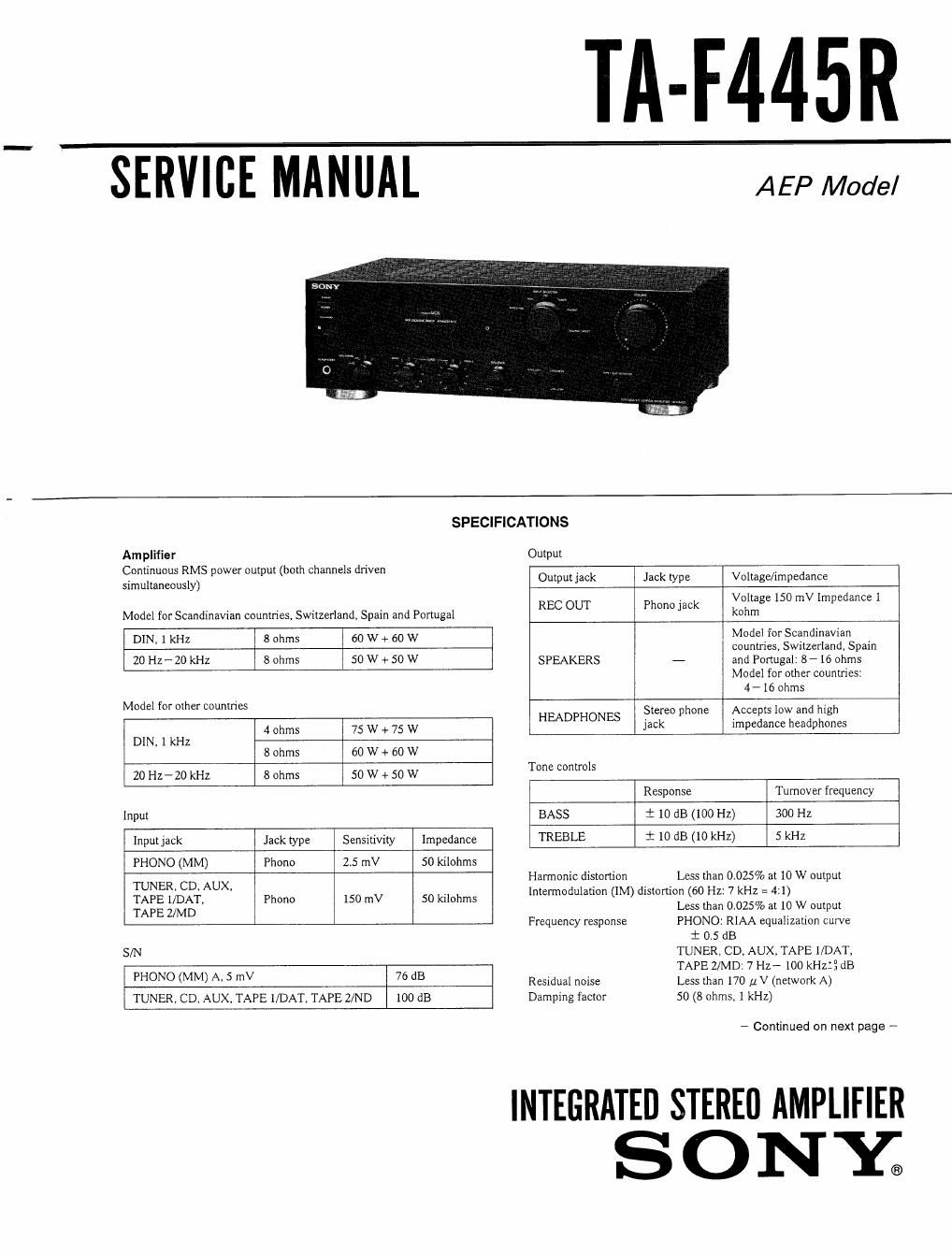
Sony ta f 445 r service manual
This is the 19 pages manual for sony ta f 445 r service manual.
Read or download the pdf for free. If you want to contribute, please upload pdfs to audioservicemanuals.wetransfer.com.
Extracted text from sony ta f 445 r service manual (Ocr-read)
Page 1
TA-F445R
SERVICE MANUAL AEP Model
SPECIFICATIONS
Amplifier Output
Continuous RMS ower out ut both channels driven , .
simultaneously) p p < Output Jack Jack type Voltage/Impedance
. Voltage 150 mV Impedance I
REJC OUT Ph k
ModeI for Scandinavian countries, Switzerland, Spain and Portugal ono Iac KDhm
DIN, 1 kHz 8 ohms 60 W + 60 W Model for Scandinavian
countries, Switzerland, Spain
20 HZ- 20 kHz 8 ohms 50 W + 50 W SPEAKERS - and Portugal: 8 - 16 ohms
Model for other countries:
4- 16 ohms
Model for other countries '
HEADPHONES stereo phone Accepts low and high
4 ohms 75 W + 75 W Jack Impedance headphones
DIN, 1 kHz
8 ohms 60 W + 60 W
20 Hz- 20 kHz 8 ohms 50 w + 50 w Tm mms
Response Turnover frequency
Input BASS i 10 dB (100 Hz) 300 Hz
Inputjack Jack type SensitIvIly Impedance TREBLE i 10 dB (10 kHz) 5 kHz
PHONO (MM) Phono 2.5 mV 50 kiIohms
Harmonic distortion Less than 0.025% at 10 W output
TUNER, CD, AUX, , » - . _ .
TAPE l/DAT, Phone 150 mV 50 @0th lntermodulation (IM) distortion (60 Hz. 7 kHz - 4.1)
TAPE Z/MD Less than 0025% at 1t) W output
Frequency response PHONO: RIAA equalization curve
i 0.5 dB
S/N TUNER, CD, AUX, TAPE l/DAT,
TAPE ZIMDI 7 Hz- 100 kHzlg dB
PHONO (MM) A' 5 mV 76 dB ResiduaI noise Less than 170 [1V (network A)
TUNER. CD, AUX, TAPE I/DAT, TAPE Z/ND 100 dB Damping factor 50 (8 ohms, 1 kHz)
- Continued on next page -
INTEGRATED STEREU AMPLIFIER
S O N E
Page 2
General
System Preamplifier: Low-noise, equalizer
amplifier
Power amplifier: Pure-complementary
SEPP OCL power amplifier with all
stages directly coupled
220 V-230 V AC, 50/60 Hz
Model forScandinavian countries,
Switzerland, Spain and Portugal
120 W
Model for other countries
180 W
Approx. 430 X 135 X 315 mm (w/h/d)
(17 X 5% X 12'/2 inches)
Approx. 66 kg (14 lb 9 oz)
Remote commander RM-S3Il (1)
Sony SUM-3 (NS) batteries (2)
Power requirements
Power consumption
Dimensions
Mass
Supplied accessories
The above values are measured at 230 V AC.
Design and specifications are subject to change without notice.
SAFETY-RELATED COMPONENT WARNINGI!
COMPONENTS IDENTIFIED BY MARK & OR DOTTED
LINE WITH MARK A ON THE SCHEMATIC DIAGRAMS
AND IN THE PARTS LIST ARE CRITICAL T0 SAFE
OPERATION. REPLACE THESE COMPONENTS WITH
SONY PARTS WHOSE PART NUMBERS APPEAR AS
SHOWN IN THIS MANUAL OR IN SUPPLEMENTS PUB-
LISHED BY SONY.
TABLE OF CONTENTS
Section M Page
Specifications --------------------------------- 1
1. GENERAL
Location of Controls ...................... 3
2. ELECTRICAL ADJUSTMENT ~~~~~~~~~~ 4
3. DIAGRAMS
3-1, IC Pin Description ------------------------ 5
3-2. Block Diagram ---------------------- . - t . . 6
3-3. Printed Wiring Boards - Panel Section - 9
3-4. Printed Wiring Boards - Main Section - . . - - 12
3-5. Schematic Diagram ----------------------- 15
4. EXPLODED VIEWS -------------------- 19
5. ELECTRICAL PARTS LIST ----------- 21
Note:
There are two type of AEP models which are depend
on countries.
AEPZ model: Model for Scandinavian countries,
Switzerland, Spain and Portugal
AEPl model: Model for other European countries