Sony ta f 420 service manual
This is the 18 pages manual for sony ta f 420 service manual.
Read or download the pdf for free. If you want to contribute, please upload pdfs to audioservicemanuals.wetransfer.com.
Extracted text from sony ta f 420 service manual (Ocr-read)
Page 1
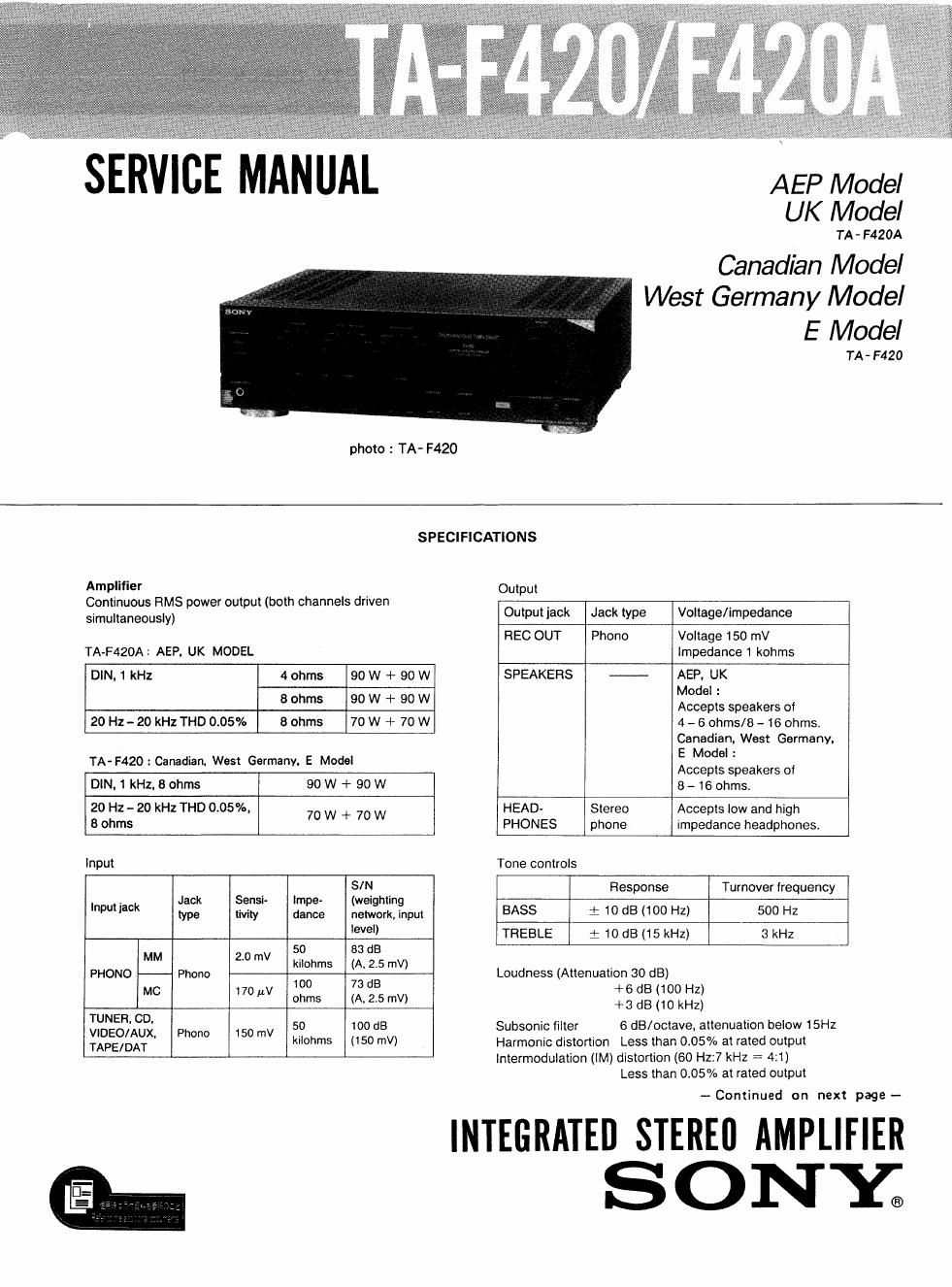
SERVICE MANUAL
photo : TA- F420
AEP Model
UK Model
TA-F420A
Canadian Model
West Germany Model
E Model
TA . F420
SPECIFICATIONS
Amplifier Output
Continuous RMS power output (both channels driven
simultaneously) Output lack Jack type Voltage/Impedance
REC OUT Phono Voltage 150 mV
TA-F420A : AEP, UK MODEL lmpedance 1 kohms
DIN,1 kHz 4 ohms 90 W + 90 W SPEAKERS - AEP. UK
Model :
8 ohms 90 W + 90 W Accepts speakers at
20 Hz-ZO kHz THD 0.05% 8 ohms 70 W + 70 W 4 - 6 ohms/8 - 16 ohms.
Canadian. West Germanv.
TA- F420 : Canadian. West Germanv. E Model E Model :
Accepts speakers of
DIN. 1 kHz. 8 ohms 90 W + 90 W 8 - 16 ohms.
20 Hz - 20 kHz THD 0.05%. 70 W + 70 W HEAD- Stereo Accepts low and high
8 ohms PHONES phone impedance headphones.
Input Tone controls
SIN Response Turnover Irequency
. Jack Sensi- Impe- (weighting
Inputiack type My dance new, in BASS : 10 dB (100 Hz) 500 Hz
90 TFIEBLE i 10 dB (15 kHz) 3 kHz
50 88 dB
MM 20 mV .
kl h A. 2.5 v ,
PHONO Phono 1'0: ms (73 as m ) Loudness (Attenuation 30 dB)
+ 6 dB 100 Hz
MC 170 W °""5 W 2'5 "0 +3 dB :10 kHz;
5323s; Phono 150 "N 50 100 dB Subsonic filter 6 dB/octave. attenuation below 15Hz
TAPE/DAT ' "0th ('50 "V) Harmonic distortion Less than 0.05% at rated output
Intermodulation (IM) distortion (60 Hz:7 kHz : 4:1)
Less than 005% at rated output
~Continued on next page-
INTEGRATED STEREI] AMPLIFIER
SONY;
Page 2
TA- F420/ F420A
Frequency response
PHONO: RIAA equalization curve
:05 dB
TUNER, CD. VIDEO/AUX, TAPE1,
TAPEZ/DAT: 7 Hz - 100 kHz 13 (18
Less than 170 av (network A)
40 (8 ohms, 1 kHz)
Residual noise
Damping factor
General
System Preamplifier: Low-noise, high»gain
equalizer amplifier
Power amplifier: Pure-complementary
SEPP OCL power amplifier with all
stages directly coupled
Power requirements AEP. West Germany Model :
220 V AC, 50 Hz
U.K. model: 240 V AC, 50 Hz
Canadian Model : 120 V AC, 60 Hz
E Model: 120 V,
220 V or 240 V AC adjustable,
50/60Hz
Power consumption AEP, West Germany Model : 150 W
UK Model: 870 W
Canadian Model : 315 VA
E Model : 155 W
Dimensions Approx. 430 X 135 X 375 mm (w/h/d)
(17 X 57/. X 14/. inches)
Weight Approx. 8.9 kg (19 lb 10 oz)
Design and specifications subject to change without notice.
Note
This appliance conforms with EEC directive 87/308/EEC
regarding interference suppression.
MODEL lDENTlFICATION
- Specification Label -
AEP, UK Model: TA-F420A
West Germany, Canadian. E Model: TA-F420
SONYo MODEL New
INTEGRATED STEREO AMPLIFIER
SERIAL NO.
MADE IN JAPAN
AEF, West Germany Model: AC:
220V~50/ 60H: 160W
UK Model: AC: 240V~50/ 60H: 370W
Canadian Model: AC: 120V 60H 315VA
E Model: AC: 120/ 220/ 240V~
50/ 60H: 160W
SAFETY CHECK-OUT
After correcting the original service problem,
perform the following safety check before releasing
the set to the customer:
Check the antenna terminals, metal trim, metallized
knobs, screws, and all other exposed metal parts for
AC leakage. Check leakage as described below.
LEAKAGE TEST
The AC leakage from any exposed metal part to
earth ground and from all exposed metal parts to any
exposed metal part having a return to chassis, must
not exceed 0.5 mA (500 microampers). Leakage
current can be measured by any one of three
methods.
1. A commercial leakage tester, such as the
Simpson 229 or RCA WT-S40A. Follow the
manufacturers instructions to use these instru-
ments,
2. A battery-operated AC milliammeter. The Data
Precision 245 digital multimeter is suitable for
this job.
3, Measuring the voltage drop across a resistor by
means of a VOM or battery-operated AC volt-
meter. The limit" indication is 0.75V, so
analog meters must have an accurate low-
voltage scale. The Simpson 250 and Sanwa
SH-63Trd are examples of a passive VOM that
is suitable, Nearly all battery operated digital
multimeters that have 3 2V AC range are
suitable. (See Fig. A)
To Exposed Meral
Part: on Set
A C
voltmeter
0.15uF
(0,75 Vl
r
gum /
L.
Earth Ground
Fig. A. Using an AC voltmeter to check AC leakage.
SAFETY-RELATED COMPONENT WARNING
COMPONENTS IDENTIFIED BV MARK A 0R DOTTED
LINE WITH MARK A ON THE SCHEMATIC DIAGRAMS
AND IN THE PARTS LIST ARE CRITICAL TO SAFE
OPERATION. REPLACE THESE COMPONENTS WITH
SONY PARTS WHOSE PART NUMBERS APPEAR AS
SHOWN IN THIS MANUAL OR IN SUPPLEMENTS PUB<
LISHED BY SONV.
ATTENTION AU COMPOSANT AYANT RAPPORT
A LA secuniré!
LES COMPOSANTS IDENTIFIES PAR UNE MARQUE A
sun LES DIAGRAMMES SCHEMATIOUES ET LA LISTE
DES PIECES som CRITIQUES POUR LA sécumré
DE FONCTIONNEMENT. NE REMPLACER css COM-
POSANTS ous PAR DES PIECES SONY DONT LES
NUMEROS SONT DONNés DANS cs MANUEL ou
DANS LES SUPPLEMENTS PUBLIES PAR SONY.