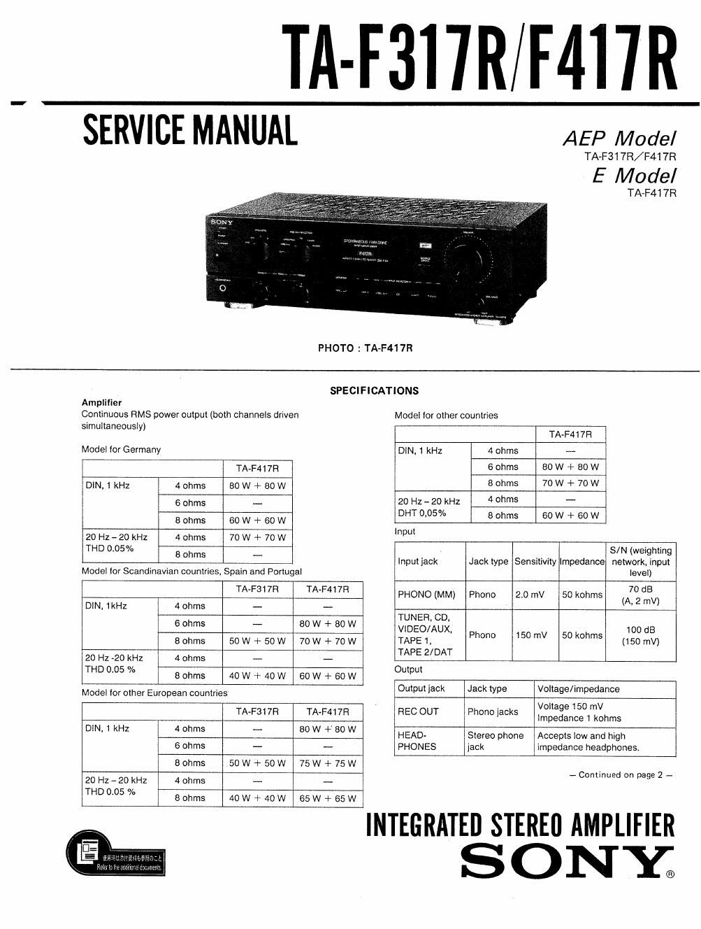
Sony ta f 317r f417rs service manual
This is the 26 pages manual for sony ta f 317r f417rs service manual.
Read or download the pdf for free. If you want to contribute, please upload pdfs to audioservicemanuals.wetransfer.com.
Extracted text from sony ta f 317r f417rs service manual (Ocr-read)
Page 2
TA-F317R/F417R
Tone controls
Response Turnover frequency
BASS :8 dB (100 Hz) 500 Hz
TREBLE 1-8 dB (15 kHz) 3 kHz
Harmonic distortion
Less than 0.05% at rated output
Intermodulation (IM) distortion (60 Hz? kHz = 4:1)
Less than 005% at rated output
PHONO: RIAA equalization curve
:05 dB
TUNER, CD, VlDEO/AUX, TAPE 1.
TAPE 2/DAT: 7 Hz - 100 kHz if dB
Less than 170 uV (network A)
40 (8 ohms, 1 kHz)
Frequency response
Residual noise
Damping factor
General
System Preamplifier: Low-noise, high-gain equalizer
amplifier
Power amplifier: Pure-complementary SEPP
OCL power amplifier with all stages
directly coupled
Power requirements AEP model : 220 V - 230 V AC, 50 HZ
E model : 120 V,
220 V or 240 V AC adjustable,
50/60 Hz
Model for Germany
TA-F417Fi: 160 W at 230 V AC
Model tor Scandinavian countries,
Spain and Portugal
TA-F317Fi: 130 W at 230 V AC
TA-F417R: 160 W at 230 V AC
Model for other European countries
TA-F317Fl: 130 W at 230 V AC
TA-F417R: 260 W at 230 V AC
Model lor other countries
TA-F417R: 130 W at 230 V AC
Approx, 430 X 135 X 315 mm (w/h/d)
(17 X 53/3 X 12% inches)
TA-F317R: Approx. 59 kg (13 lb 1 oz)
TA-F417Ft: Approx. 7.4 kg (16 lb 5 02)
Remote commander FlM»8310 (1)
Sony SUM-3 (NS) batteries (2)
Power consumption
Dimensions
Weight
Accessories
Design and specilications subject to change without notice.
Note
This appliance conforms with EEC Directive, 87/308/ EEC regarding
interference suppression
TABLE OF CONTENTS
Section Title
Specifications . ................. . .........
Model Identification
Precautions ~~~~~~~~~~~~~
1. GENERAL
Parts Identification ....................................................... 4
2. DISASSEMBLY ..................... .................................. 5
3, ADJUSTMENTS. ................ ................. ~~~6
4. DIAGRAMS
4-1 Circuit Boards Location
4~2. Semiconductor Lead Layouts
4-3. Printed Wiring Boards ---------
4-4, Schematic Diagrams (F3171?)
4'5. Schematic Diagrams (F417R)
5 EXPLODED VIEWS ................................... . .............. 25
6. ELECTRICAL PARTS L|ST .......... . .............. ..... ........ 28