Sony ta f 303 esd service manual

This is the 24 pages manual for sony ta f 303 esd service manual.
Read or download the pdf for free. If you want to contribute, please upload pdfs to audioservicemanuals.wetransfer.com.

Page: 1 / 24
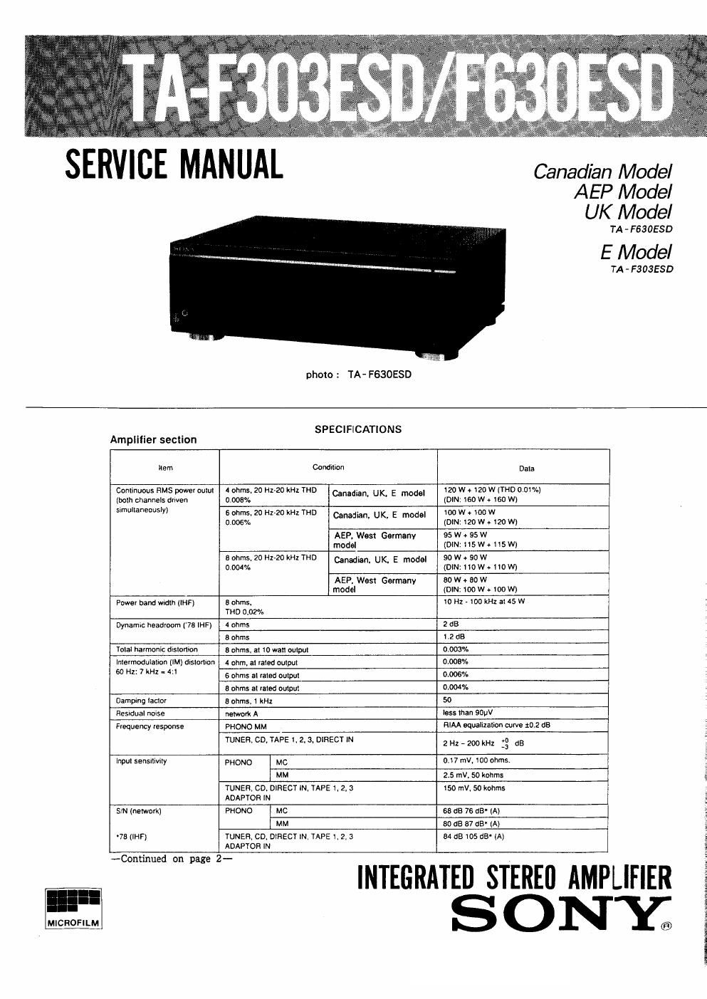
sony ta f 303 esd service manual

Extracted text from sony ta f 303 esd service manual (Ocr-read)


Page 2

TA- F303ESD/ F630ESD

Data

l50 mV, I kohm

Item Condition
Output voltage Impedance REC our 1,2,3
ADAPTOR OUT
HEADPHONES

25 miliwalts (at 5 ohms)
Accepts low and high impedance headphones.

Tone controls BASS, at 00 Hz

26 dB
(turnover lreq. 400 Hz)

TREBLE. al 10 kHz 26 dB
(Iraq 4 kHz)
DA converter section
Ilarn Condition Data
Input sensitrvrty DIGITAL COAXIAL IN 0.5 Vp-p, t20/.. 75 ohms
DIGITAL OPTICAL IN I, 2 TOSLINK
Oulput voltage impedance DIGITAL OPTICAL 2 REC OUT TOSLINK
Output voltage DA converter 2 V
General AC outlet
System Preamplifier section: Low-noise high gain NFB type Culadian model 2 switched. unswilched,
equalizer amplifier. passive type direct tone control 100 wans mu each
Power amplifier section: Purecomptementary SEPP AEP UK
power amplifier West Germany modal
. E model I Swllched, t unswrtched.
Power requirements 100 watts each
AEP. West Germany model : 220 V AC, 50 Hz
u K mode|1240 v Ac, 50 Hz . .
E model : 120 V, 220 V or 240 V AC Dimensons

adjustable. 50/60 Hz
Canadian model: 120 V, AC. 50/50H2

Power consumption

Canadian model 510 VA
AEP. UK.

220 W
West Gormanv modal
UK model 500 W
E model 340 W

Approx 430 x ISO x390 mm (w/h/d)
( 17 x 5% XISVI inches)
r ,

Weight
Approx. 13.7 kg (30 lbs 4 oz) net

MODEL IDENTIFICATION
-- Specification Label -

SONYo MODEL N0.

INTEGRATED STEREO AMPLIFIER

/

SERIAL No,
MADE IN JAPAN

AEP. West Germany Model: AC: 220 V ~ 50/60 Hz
UK Model: AC: 240 V ~ 50/60 Hz
E Model: AC: 120/220/240 V
~ 50/60 Hz
Canadian Model : AC : 120V 60Hz

TABLE OF CONTENTS

Section m1}. pig:
Specification............................. ............... 1
Model Identification ........................ . ............ 2
Safety Check-Out . . . . ................ . . . . 2
On Operating Voltage
1. GENERAL

Parts Identification . . . . .. ................. . .......... 4
2. ELECTRICAL ADJUSTMENTS ----- --------------- 5
3. DIAGRAMS

3- 1. Schematic Diagrammp (Amp Section) ..... 7

3'2- Printed Wiring Boards (Amp Section) -------- ~ 11

3-3. Printed Wiring Boards

(D/A Converter Section) ' , 16

3-4. Schematic Diagram (D/ A Converter Section) 18
4_ EXPLODED VIEWS ..... ................... 22
5. ELECTRICAL PARTS LIST -------------- ------- .. 25