Sony ta f 222 esr service manual

This is the 25 pages manual for sony ta f 222 esr service manual.
Read or download the pdf for free. If you want to contribute, please upload pdfs to audioservicemanuals.wetransfer.com.

Page: 1 / 25
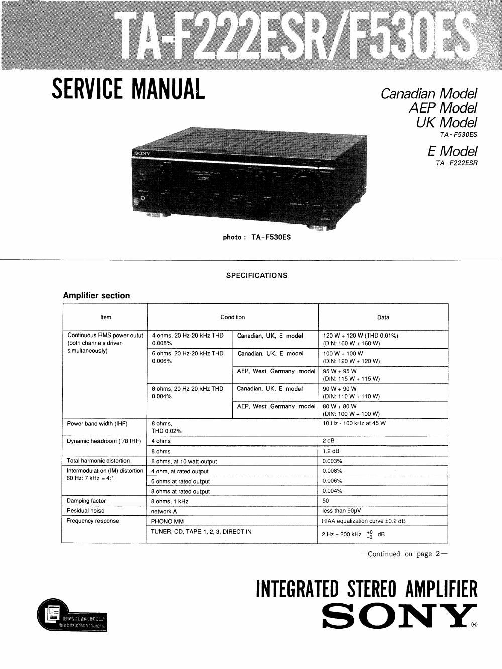
sony ta f 222 esr service manual

Extracted text from sony ta f 222 esr service manual (Ocr-read)


Page 2

TA- F222ESR/ F530ES

Item Condition Data
Input sensiiivity PHONO MC 0.17 mV, 100 ohms
MM 2.5 mV, 50 kohms
TUNER, CD, DIRECT IN, TAPE 1. 2, 3 150 NV, 50 kohms
ADAPTOR IN
S/N (network) PHONO MC 68 dB 76 dB* (A)
MM 80 dB 87 dB* (A)
78 (IHF) TUNER. CD, DIRECT IN, TAPE 1. 2, 3 84 dB 105 (113* (A)
ADAPTOR IN
Output voltage impedance REC OUT 1, 2, 3 150 mV, 1 kohm
ADAPTOR OUT
HEADPHONES 25 miliwatts (at 8 ohms)

Accepts low and high impedance headphones.

Tone controls BASS, at 100 Hz

16 dB
(turnover freq. 400 Hz)

TREBLE, at 10 kHz :6 dB
(freq. 4 kHz)
General
System Preamplifier section: Low~noise high gain NFB type AC outlet
equalizer amplifier. passive type direct lone control Canadian model 2 swilched, 1 unswitched,
Power amplilier section: Purecomplementary SEPP 100 walls '"EX- 930
power amplifier AEP. UK.
Wesr Germany model _
Power requirements E model 1 swilched,1 unswitched,
AEP, West Germany model : 220 V AC, 50 Hz 100 walls each
U K model: 240 V AC, 50 Hz
E model : 120 V, 220 V or 240 V AC
adjustable, 50/60 Hz Dimensions

Canadian model: 120 V AC, 50/60Hz

Power consumption

Canadian model 510 VA
AEP, UK.

22
West Germany model 0W
UK model 600 W
E model 340 w

Approx. 430 x 150 x 370 mm (w/h/d)
(17 x 5% x 149/15 inches)

Weight
Approx. 135 kg (29 lbs 13 02) net

MODEL IDENTIFICATION
- Specification Label --

SONYO MODEL N0.
STEREO CASSETTE DECK

k\\\\\\\\\\\\\\\\\\\\\\\\\\

AC 120V 60Hz
AC 220V~50/60Hz
AC 240V~50/60Hz

Canadian model 3
AEP, West Germany model 1

UK model :
E model 2

AC 120/220/240V~50/60Hz '

TABLE OF CONTENTS

Section Tit-1e FAKE!
SpecificatiOn ............................................ 1
Model Identification ..................................... 2
Servicing Notes ......................................... 3
1. GENERAL

Parts Identification .................................. 4
2. ELECTRICAL ADJUSTMENTS ......................... 5
3. DIAGRAMS

3-1. Printed Wiring Boards - 8

3-2, Schematic Diagram ............................. 13
4. EXPLODED VlEWS ................................... 17
5, ELECTRICAL PARTS LIST ............................ 19

_2_