Sony ta f 170 240

This is the 16 pages manual for sony ta f 170 240.
Read or download the pdf for free. If you want to contribute, please upload pdfs to audioservicemanuals.wetransfer.com.

Page: 1 / 16
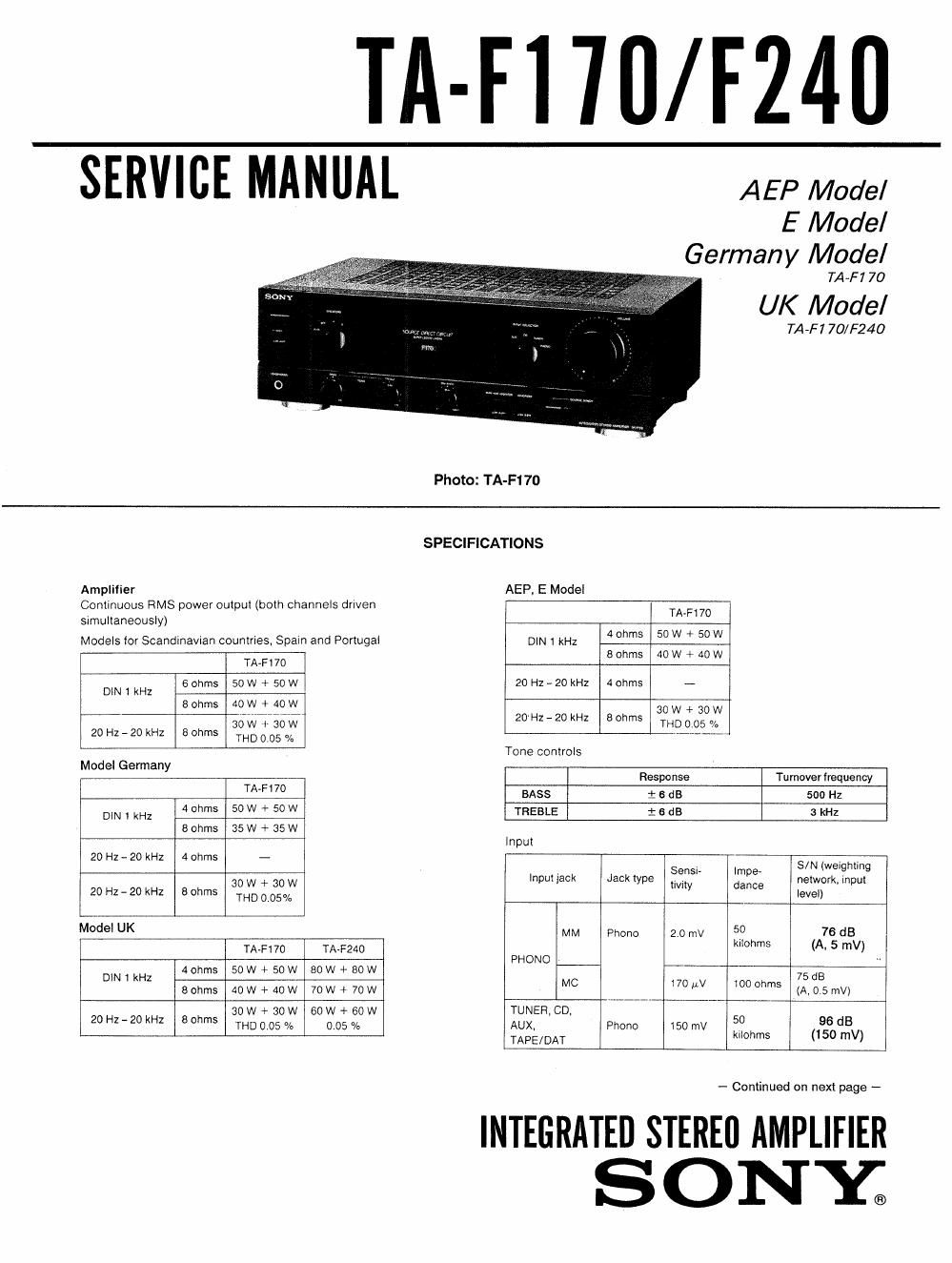
sony ta f 170 240

Extracted text from sony ta f 170 240 (Ocr-read)


Page 2

TA-F1 70/ F240

Output
Output jack Jack type Voltage/ impedance
Voltage 150 mV
REC OUT Phono impedance 1 kohms
Model tor Scandinavian countries.
Spain and Portgul
Accepts speakers of
SPEAKERS -- 6 - 16 Ohms.
Models tor other countries
Accepts speakers ol
4 - 16 ohms
HEAD- S h Accepts low and high impedance
PHONES tereo p one headphones

Loudness (Attenuation 30 dB)
+6 dB (100 Hz)/+3 dB (10 kHz)
Subsonic filter 6 dB/octave, attenuation below 15Hz

lntermodulation (IM) distortion (60 HZ: 7 kHz=4: 1)
Less than 0.05% at rated output
Frequency response
TUNER, CD. AUX. TAPEI/DAT:
7Hz- 100kH213dB
Less than 190 H V (network A)
40 (8 ohms, 1 kHz)

Resid ual noise
Dampong factor

Power requirements AEP, Germany models:

220 - 230 V AC. 50 Hz
UK model: 240 V AC, 50 Hz
E model: 120 V.

220 V or 240 V AC adjustable, 50/60 Hz

MODEL IDENTIFICATION
~ Specification Labels -

TA-F1 70
TA-F?40

m

SONY®
STEREO CONTROL AMPLIFIER

MODEL N0.

SERIAL No.
MADE IN JAPAN

AEP, Germany model: AC:

TA-F17O UK model: AC: 240 V ~50/60 HZ 250 W

TA-F240 UK model: AC: 240 V ~50/60 Hz 380 W

E model: AC: 120/220/240 V ~50/60 Hz
90 W

PHONE: RIAA equalization curve i 0.5 dB

220 - 230 V~50/60Hz 90 W

Power consumption

Models for F170 F240
UK 250 W 380 W
Germany 95 W -
AEP. E 90 W -
Dimensions Approx. 430 X 135 X 312 mm (w/h/d)

(17 X 51. X 123/. inches)
TA-F170: Approx. 76 kg (16 lb 12 oz)
TA-F240: Approx. 8 kg (17 lb 10 oz)

' For all the countries except UK, and Canada. the above values
are measured at 230 V AC.

Weig ht

Design and specifications subject to change without notice,

Note
This appliance contorms with EEC directive 87/308/EEC regarding
interlerence suppression,

TABLE OF CONTENTS

Section Title Page
Specifications ...................... 1
Model Identification 2
Precautions .................................... 3
1, GENERAL ............................. 4

Connections .................. . ...... . . . . 4

Parts Identification ~~~~~~~~~~~~~~~~~~~~~~~~ 4
2. DISASSEMBLY ......................... 5
2-1. Disassembly Of Front Panel ~~~~~~~~~~~~~~~ ~ 5
3. ELECTRICAL ADJUSTMENTS ~~~~~~~~ 5
4. DIAGRAMS ....................... 6
4-1. Block Diagram - t - - 6
4-2 Printed Wiring Boards 3
4-3. Schematic Diagram .................... 11
5- EXPLODED VIEWS .................... 14
6. ELECTRICAL PARTS LIST ~~~~~~~~~~~~ 16

SAFETY-RELATED COMPONENT WARNING

COMPONENTS IDENTIFIED BV MARK A OR DOTTED
LINE WITH MARK A ON THE SCHEMATIC DIAGRAMS
AND IN THE PARTS LIST ARE CRITICAL TO SAFE
OPERATION. REPLACE THESE COMPONENTS WITH
SONV PARTS WHOSE PART NUMBERS APPEAR AS
SHOWN IN THIS MANUAL OR IN SUPPLEMENTS PUB-
LISHED BY SONY.

ATTENTION AU cOMPQSANT AYANT RAPPORT
A LA SECURITE!

LES COMPOSANTS IDENTIFIEs PAR UNE MAROUE [1;
sun LES DIAGRAMMES SCHEMATIOUES ET LA LISTE
DES PIECES SONT CRITIQUES POUR LA sécuaITé
DE FONCTIONNEMENT. NE REMPLACER CES COM-
POSANTS OUE PAR DES PIECES SONY DONT LES
NUMEROS SONT DONNEs DANS CE MANUEL ou
DANS LES SUPPLEMENTS PUBLIEs PAR soNv.