Sony ta f 120a f220a service manual

This is the 15 pages manual for sony ta f 120a f220a service manual.
Read or download the pdf for free. If you want to contribute, please upload pdfs to audioservicemanuals.wetransfer.com.

Page: 1 / 15
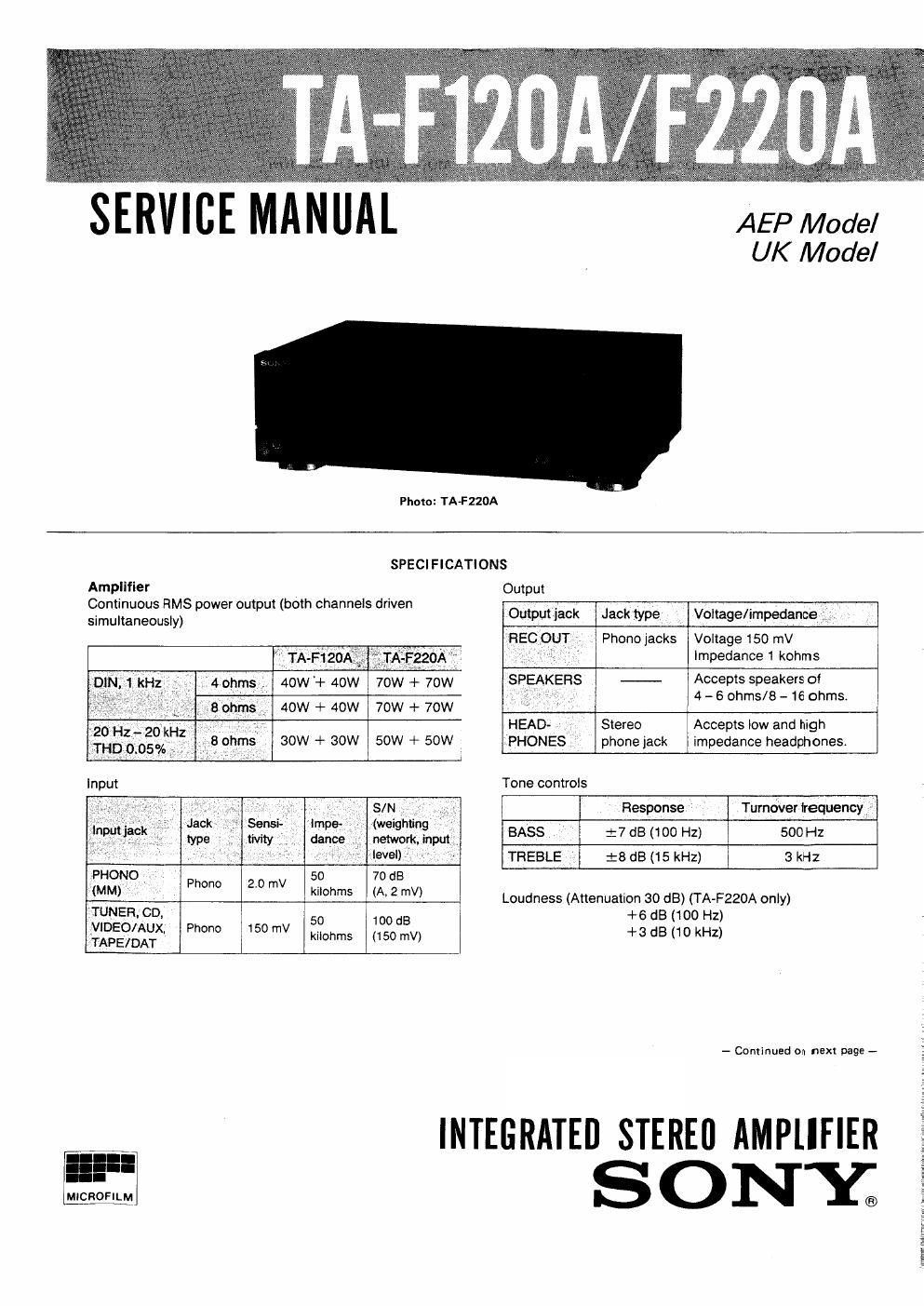
sony ta f 120a f220a service manual

Extracted text from sony ta f 120a f220a service manual (Ocr-read)


Page 2

TA-F120A/F220A

Harmonic distortion Less than 0.05% at rated output MODEL IDENTIFICATION
intermodulation (iM) distortion (60 Hz:7 kHz = 4:1) _ Specificatign Label _
Less than 0.05% at rated output
Frequency response
P:(gi:%BRIAA equalization curve S OIQY0 MODEL N O.
TUNER, CD, VIDEO/AUX, TAPE1,
TAPE2/DAT: 7 Hz _100 kHz :3 dB INTEGRATED STEREO AMPLIFIER
Residual noise Less than 170 /LV (network A)
Damping factor 40 (8 ohms, 1 kHz)
General
System Preamplifier: Low-noise, high-gain
equalizer amplifier SERIAL NO.
Power amplifier: Pure-complementary MADE lN JAPAN
SEPP OCL power amplifier with all
stages directly coupled
Power requirements AEP model: 220V AC, 50Hz TA-F120A
UK model: 240V AC. 50 Hz TA-FZZOA
Power consumption AEP model:
TA-F120A: 95W AEP Model: AC: 220 V V 50/60 Hz
TA-FZZOA: 150W UK Model: AC: 240 v ~ 50/60 Hz
U K model:
TA»F12OA: 230W
TA-F220A: 380W
Dimensions Approx, 430 X 135 X 315 mm (w/h/d)
(17 X 5 /. X 12 /z inches)
Weight AEP model:

TA-F120A: Approx. 5.7 kg (12 lb 9 oz)

TAvF220A1Approx, 7.4 kg (16 lb 5 02)
UK model:

TA-F120A: Approx. 5.6 kg (12 lb 6 oz)

TA-F220A: Approx. 68 kg (15 lb)

Design and specifications subject to change without notice
Note

This appliance conforms with EEC directive 87/308/EEC
regarding interference suppression.

TABLE OF CONTENTS

Section Title Page

Specifications ......................... 1

Model Identification ------------------- 2

SECTION 1. GENERAL
l-I. Parts Identification ~ 3
l~2. Connections ----------- 3

SECTION 2. BLOCK DIAGRAM ~~~~~~~~~~~ 4 SAFETY-RELATED COMPONENT WARNINGI!

SECT'ON 3~ ELECTRICAL ADJUSTMENTS 5 COMPONENTS IDENTIFIED av MARK A on DOTTED

SECTION 4. DIAGRAMS LINE WITH MARK A ON THE SCHEMATIC DIAGRAMS
4_1_ Circuit Boards Location ......... 5 AND IN THE PARTS LIST ARE CRITICAL T0 SAFE
442. Semiconductor Lead Layouts ...... 5 OPERATION. REPLACE THESE COMPONENTS WITH
4-3. [C Block Diagrams _______________ 6 SONV PARTS WHOSE PART NUMBERS APPEAR AS

SHOWN IN THIS MANUAL OR IN SUPPLEMENTS PUB-

4-4. Printed Wiring Boards ----------- 8 LISHED By SONY.
4A5. Schematic Diagram ------------ 13

SECTION 5. EXPLODED VIEWS --------- 15

SECTION 6. ELECTRICAL PARTS LIST ' - 18