Sony ta f 120 a service manual

This is the 13 pages manual for sony ta f 120 a service manual.
Read or download the pdf for free. If you want to contribute, please upload pdfs to audioservicemanuals.wetransfer.com.

Page: 1 / 13
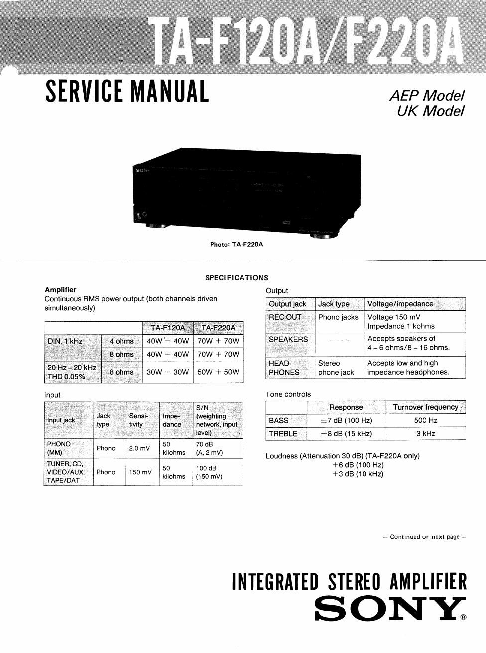
sony ta f 120 a service manual

Extracted text from sony ta f 120 a service manual (Ocr-read)


Page 2

TA-F120A/F220A

Harmonic distortion Less than 0.05% at rated output
lntermodulation (lM) distortion (60 H227 kHz = 4:1)
Less than 0.05% at rated output
Frequency response
PHONO: RlAA equalization curve
:015 dB
TUNER, CD, VIDEO/AUX, TAPE1,
TAPEZ/DAT: 7 Hz - 100 kHz :3 dB
Less than 170 uV (network A)
40 (8 ohms 1 kHz)

Residual noise
Damping iactor

General
System Preamplifier: Low-noise, high-gain
equalizer amplifier
Power amplifier: Pure-complementary
SEPP OCL power amplifier with all
stages directly coupled
Power requirements AEP model: 220V AC, 50Hz
UK model: 240V AC, 50Hz
Power consumption AEP model:
TA-F120A: 95W
TA-F220A: 150W
U K model:
TA-F120A: 230W
TA-F220A: 380W

Dimensions Approx: 430 X 135 X 315 mm (w/h/d)
(17 X 5% X 12 /2 inches)
Weight AEP model:

MODEL IDENTIFICATION
- Specification Label -

S ONYo

INTEGRATED STEREO AMPLIFIER

MODEL NO.

SERIAL NO.
MADE IN JAPAN

TA-F1 20A
TA-FZZOA

AEP Model: AC: 220 V ~ 50/60 Hz
UK Model: AC: 240 V ~ 50/60 HZ

TA-F120A: Approx, 5.7 kg (12 lb 9 oz)

TA-F220A: Approx. 7.4 kg (16 lb 5 02)
UK model:

TA-F120A: Approx: 56 kg (12 lb 6 oz)

TA-F220A: Approx. 6.8 kg (15 lb)
Design and specifications subject to change without notice.
Note

This appliance conforms with EEC directive 87/308/ EEC
regarding interference suppression.

TABLE OF CONTENTS

Section Title Page
Specifications ~~~~~~~ 1
Model Identification ------------------- 2
SECTION 1. GENERAL
l-l. Parts Identification ----------- 3
I-Z. Connections ..................... 3
SECTION 2. BLOCK DIAGRAM ............ 4

SECTION 3. ELECTRICAL ADJUSTMENTS -~ 6
SECTION 4. DIAGRAMS


4-]. Circuit Boards Location ------- 6
4-2. Semiconductor Lead Layouts ~~~~~~ 6
4-3. IC Block Diagrams --------- r 6
4-4, Printed Wiring Boards 8
4-5. Schematic Diagram ~~~~~ 13
SECTION 5. EXPLODED VIEWS ~~~~~~~~ 16
SECTION 6. ELECTRICAL PARTS LIST ' ' 13

SAFETY-RELATED COMPONENT WARNING! I

COMPONENTS IDENTIFIED BV MARK & OR DOTTED
LINE WITH MARK A ON THE SCHEMATIC DIAGRAMS
AND IN THE PARTS LIST ARE CRITICAL TO SAFE
OPERATION. REPLACE THESE COMPONENTS WITH
SONY PARTS WHOSE PART NUMBERS APPEAR AS
SHOWN IN THIS MANUAL OR IN SUPPLEMENTS PUB-
LISHED BY SONY.