Sony ta f 101 r service manual

This is the 14 pages manual for sony ta f 101 r service manual.
Read or download the pdf for free. If you want to contribute, please upload pdfs to audioservicemanuals.wetransfer.com.

Page: 1 / 14
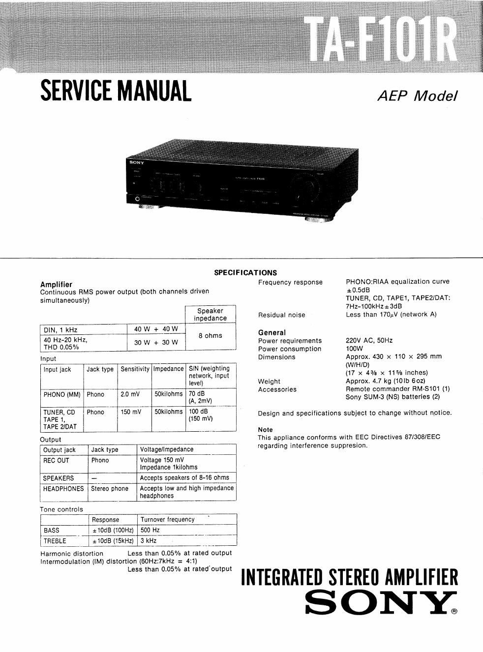
sony ta f 101 r service manual

Extracted text from sony ta f 101 r service manual (Ocr-read)


Page 1

SERVICE MANUAL AEP Model

SPECIFICATIONS
Amplifier Frequency response PHONO:RIAA equalization curve
Continuous RMS power output (both channels driven :0.5dB
simultaneously) TUNER, CD, TAPEt, TAPEZIDAT:
7Hz-100kHz¢3dB
$592239 Residual noise Less than 170W (network A)
40 W
DIN, 1 kHz 40 W + 8 ohms General
$gszgg5Hz, 30 W + 30 W Power requirements 220V AC, 50Hz
D ° Power consumption 100W
Input Dimensions Approx. 430 x 110 x 295 mm
In ut 'ack Jack t e Sensitivit Im edance SIN wei htin (IN/HID)
p l yp y p netvIork,ginpu% (17 x 4% x 115/3 inches)
level) Weight Approx 4.7 kg (tolb 602)
, Accessories Remote commander RM-Stot (1)

PHONO (MM) Phono 20 mV 50kiiohms xii Sony SUM»3 (N8) batteries (2)
$155100 Ph°° 15° "W 50th (110500drrEIV) Design and specifications subject to change without notice.
TAPE 2IDAT

Note

Output This appliance conforms with EEC Directives 87/308/EEC
Output lack Jack type Voltage/impedance regarding interference suppresron.

REC OUT Phono Voltage 150 mV

Impedance 1kilohms
SPEAKERS - Accepts speakers of 8-16 ohms
HEADPHONES Stereo phone Accepts low and high impedance
headphones
Tone controls
Response Turnover frequency

BASS 210dB (tOOHz) 500 Hz
[EBLE :IOdB (15kHz) 3 kHz

Harmonic distortion Less than 0.05% at rated output

intermodulation (IM) distortion (60Hz:7kHz = 4:1)

3 INTEGRATED STEREII AMPLIFIER

SONY;

Page 2

TA-F1 01 R

TABLE OF CONTENTS

Section Title Page
Specifications ..................................................................... 1
1. GENERAL

1-1. Parts Identification


1-2, Connectionsmn ..4
2. DIAGRAMS

2.1_ Circuit Boards Locationm .................. . .................... 5

2-2. Semiconductor Lead Layouts- ~-6

273. Printed Wiring Boards~.......... ..

24, Schematic Diagram ............... . ............................... 11
3 EXPLODED VIEWS .............................. ................. 15
4, ELECTRICAL PARTS Llsr........ .......... . ................. "17

SAFETY-RELATED COMPONENT WARNING

COMPONENTS IDENTIFIED BV MARK A 0R DOTTED
LINE WITH MARK A ON THE SCHEMATIC DIAGRAMS
AND IN THE PARTS LIST ARE CRITICAL TO SAFE
OPERATION. REPLACE THESE COMPONENTS WITH
SONY PARTS WHOSE PART NUMBERS APPEAR AS
SHOWN IN THIS MANUAL OR IN SUPPLEMENTS PUB-
LISHED BY SONY.