Sony ta ex 9 service manual

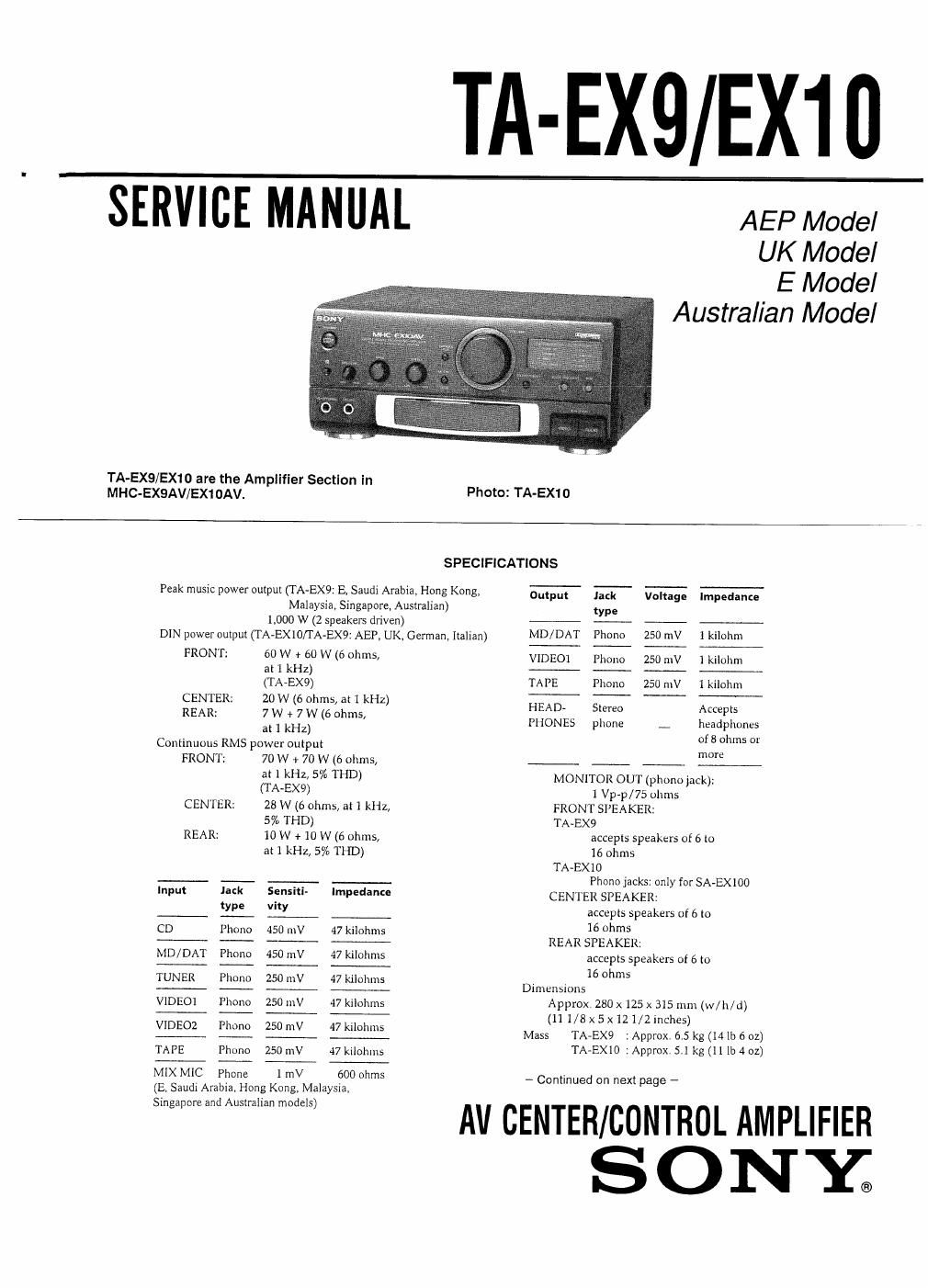
This is the 26 pages manual for sony ta ex 9 service manual.
Read or download the pdf for free. If you want to contribute, please upload pdfs to audioservicemanuals.wetransfer.com.

Page: 1 / 26
sony ta ex 9 service manual

Extracted text from sony ta ex 9 service manual (Ocr-read)


Page 2

General
Power requirements
AEP, UK, German. Italian model:
220 - 230 V AC, 50/60 Hz
E, Saudi Arabia, Hong Kong, Malaysia, Singapore,
Australian model:
110 -120V orZZO - 240 VAC
adjustable, 50/60 Hz

TABLE OF CONTENTS

Section Title Page

Specifications -------------------------------
1 . GENERAL .............................

2. DIAGRAMS
Zr]. 1C Pin Function Description ----------------
2-2, Block Diagam -------------------------
2~3I Circuit Boards Location -------------------
2-4I Printed Wiring Boards - Main Section ~ - ~ ~ ~
Z-S. Schematic Diagram - Main Section -
2~6. Schematic Diagram - Panel Section - ~~~~~~
2-7. Printed Wiring Boards - Panel Section -

3. EXPLODED VIEWS --------------------

4. ELECTRICAL PARTS LIST ------------

MODEL IDENTIFICATION
e Model Number Label -

TA-EX9: AV CENTER AMPLIFIER
TA-EXIO: AV CONTROL AMPLIFIER

SONSfo

MODEL NO.

WWW

WW

TA-EX9
AEP model: AC 220 - 230 V ~50/60 HZ 200 W
UK model: AC 220 - 230 V ~50 Hz
German, Italian model:
AC 220 7 230 V ~50 Hz 200 W
E, Saudi Arabia,Hong Kong, Malaysia,
Singapore, Australian model:

AC 110 - 120/220 - 240 V ~50/60 H2 200 W

TA-EX10
AEP model: AC 220 - 230 V ~50/60 Hz 85 W
UK model: AC 220 - 230 V ~50 Hz
German, Italian model:
AC 220 - 230 V ~50 Hz 85 W
E, Saudi Arabia,Hong Kong, Malaysia,
Singapore, Australian model:

AC 110 - 120/220 - 240 V ~50/60 HZ 85 W

I

TA-EX9/EX10

SAFETY-RELATED COMPONENT WARNINGl!

COMPONENTS IDENTIFIED BY MARK A OR DOTI'ED
LINE WITH MARK A ON THE SCHEMATIC DIAGRAMS
AND IN THE PARTS LIST ARE CRITICAL TO SAFE
OPERATION. REPLACE THESE COMPONENTS WITH
SONY PARTS WHOSE PART NUMBERS APPEAR AS
SHOWN IN THIS MANUAL OR IN SUPPLEMENTS PUB-
LISHED BY SONY.

SECTION 1
GENERAL

This section is extracted from
instruction manual.

Index to Parts and
Controls

Remote sensor
SYSTEM POWER switch and

ON/STAN'DBY indicator (7)

The indicator remains lit as long as the

AC power cord is connected to a wall

outlet.
[El Mic LEVEL control (21) (E, EA. MY, SP, HK, AUS)
E BASS control (20)
TREBLE control (20)
E KARAOKE PON button- (21) (E, EA, MY, SP, HK, AUS)
VOLUME control (5, 7, 20)
SOURCE DIRECT button (20)
IE] PRO LOGIC MODE indicators (21)
IEI osr MENU indicators (20)
05? button (20)
HEADPHONES jack (20, 24)
Mlx MIC jack (phone jack) (21,22)

(E, EA, MY, SP, HK, AUS)

MUTING button (20)
isplay window (20)
DOLBY PRO LOGIC button (21)
FUNCTION buttons (16, 19,24)

VIDEO (24)

AUDIO (16,19,24)

I Abbreviation
AUS :Australian
EA : Saudi Arabia
HK : Hong Kong
MY 1 Malaysia
SP :Singapore

_2_