Sony ta e 100ex avr service manual

This is the 26 pages manual for sony ta e 100ex avr service manual.
Read or download the pdf for free. If you want to contribute, please upload pdfs to audioservicemanuals.wetransfer.com.

Page: 1 / 26
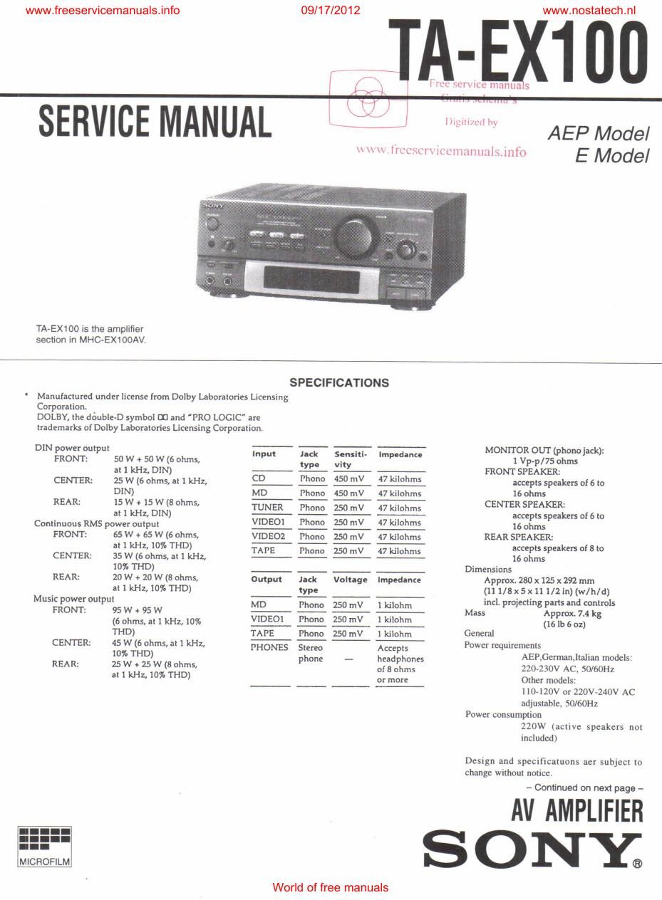
sony ta e 100ex avr service manual

Extracted text from sony ta e 100ex avr service manual (Ocr-read)


Page 1

09/17/2012 www.nostatech.nl

{I 7T l:ct- , fl
" l

SERVICE MANUAL 3: "

\,\\\\\ Irct'x'm lCLlllilIlllilISJllIO

www.freeservicemanuals.info

mu V

lhgllt/ctl My

AEP Model
E Model

TA-EX100 is the amplifier
section in MHC~EX1OOAV

SPECIFICATIONS
Manufactured undtr license from Dolby Laboratories Licensing
Corporation.
DOLEY the double-D symbol m and "PRO LOGIC" are
trademarks of Dolby Laboratories Licensing Corporation,
DIN ower out ut _. _ MONITOR 0UT( honojack):
grow: P 50 w 9 so w (6 ohms, '"P" i": 33 '""d'" l Vp-p/755hms
at 1 kHz, DlN) y -y- - FRONT SPEAKER:
CENTER: 25 W (6 ohms, at 1 kHz, CD- M m m accepts speakers of 6 to
DIN) MD Phano 450 mV 47 kilohms 16 ohms
REA R: 15 W t 15 W (8 ohms, W Phone w m CENTER SPEAKER:
at 1 kHz, DlN) -- - '- accepts speakers of 6 to
Continuous RMS power output VIDEOI Phuno 50 mV 7 3th 16 ohms
FRONT: 65 W fi 65 W (6 Ohms, VIDEOZ Phono 150 mV 47 kilohms REAR SPEAKER:
at 1 kHz, 107: THD) - - .- acce tss takers on; to
CENTER: 35 w (5 ohms, at 1 kHz, K Ph°n° w M 16 oIImsp
10% THD) Dimensions
REAR: 29 W + 20 W (3 Ohmsz Output )xk Voltage Impedance Approx. 280 x 125 x 292 mm
atl kHz,10%THD) type (11 l/8x5x11 1/2 in) (w/h/d)
Music power output - _- ~_- incl. ro'ectin arts and controls
FRONT: 95 w + 95 w MD- thm 55m- w Mass P I 3:12pm. 7.4 kg
(6 ohms, at 1 kHz, 10% VIDEO] Phone 250 mV 1 kilohm (16 lb 6 oz)
THD) TAPE Phono 250 mV l kilohm General
CENTER: 45 W (6 ohms, at 1 kHz, PHONES Stereo Accepts Power requirements
10% THD) phone _ headphones AERGermathalian models:
REA R: 25 W + 25 W (8 ohms. of 8 ohms 220-230v AC. 50/6on
at 1 kHz, 10% THD) or more Other models:

MICHOFILM

l lO-IZOV or 220V-240V AC
adjustable, 50/60Hz

Power consumption
220W (active speakers not
included)

Design and specificatuons aer subject to
change without notice

- Continued on next page -

AV AMPLIFIER

ONY;

World of free manuals

Page 2

www.freeservicemanuals.info

[ TEST MODE ]
Press SYSTEM POWER button. turn the power on and pressl DIS
PLAY an_ buttons for two seconds at the same time to

enter in the test mode,
See the list below for check of mode and display.

Button Display(mode)
PRO-LOGIC ONIOFF & MODE setting.
The display will change every pressing the
M,MENU buttont
PHANTOM(0N)-> NORMAL-v WIDE-v
SCH LOGIC-.THROUGH(OFF)
EFILE 7kHz LPF ON/OFF
PRO LOGIC B DECODER ON/OFF
MiSOURCE LEFT (Lch test tone output)
PRESENSE RIGHT (Rch test tone output)
MEMORY CENTER (Cch test [one output)
NAME REAR (Sch test [one output)
KARAOKE
FL & LED all light up
PON/MPX

Note:

Turn off the test tone with pressing the M.MENU button to change
the mode.

Press the corresponded button to each channel to fix each

channel of the test [one after the M.SOURCE buttoni
Press the SYSTEM POWER button to cancel the test mode.

SAFETY-RELATED COMPONENT WARNING I!

COMPONENTS IDENTIFIED BV MARK A OR DOTTED
LINE WITH MARK A ON THE SCHEMATIC DIAGRAMS
AND IN THE PARTS LIST ARE CRITICAL TO SAFE
OPERATION. REPLACE THESE COMPONENTS WITH
SONV PARTS WHOSE PART NUMBERS APPEAR AS
SHOWN IN THIS MANUAL OR IN SUPPLEMENTS
PUBLISHED BY SONY.

09/1 7/2012

www.nostatech.n|

TABLE OF CONTENTS
SECTION 1. GENERAL ................................................. 3

SECTION 2. DISASSEMBLY
2- It Front Panel Assembly .........
272. Audio Board and DSP Board i
2-3. Main Board ...............
2-4. Back Panel Assembly


amps.

SECTION 3. DIAGRAMS
3-li Circuit Boards Location 6
3-2. lC Pin Function

- IC6OI System Control (HD6433927BQ7F) .
3-3. Printed Wiring Board - Main Section - ,.
3»4. Schematic Diagram - Main Section - ........
375. Schematic Diagram 7 Audio/Panel Section
3-6. Printed Wiring Board 7 Audio/Panel Section -
3-7. Printed Wiring Board - DSP Section -
3-8, Schematic Diagram - DSP Section -
3-9. IC Block Diagrams - DSP Section -


SECTION 4. EXPLODED VIEWS
4-1. Front Panel Section 1
4-2. Front Panel Section 2
4-3. Chassis Section

SECTION 5. ELECTRICAL PARTS LIST ................ 38

MODEL IDENTIFICATION

- BACK PANEL -
PARTS ND,
L__.I I_I

MODEL PARTS No.
AEP model
German model 4-978-785-0C]
Italian model
Singapore model 4-9787785- 1 CI
Hong Kong model 4-978-785-2CI

World of fgee manuals