Sony ta dx 8 service manual

This is the 16 pages manual for sony ta dx 8 service manual.
Read or download the pdf for free. If you want to contribute, please upload pdfs to audioservicemanuals.wetransfer.com.

Page: 1 / 16
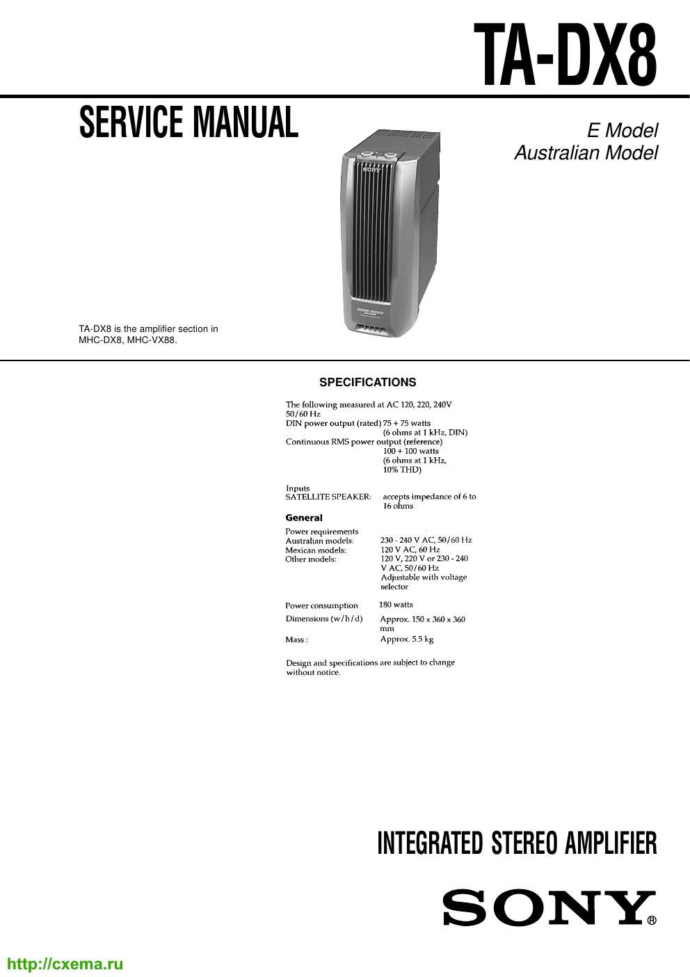
sony ta dx 8 service manual

Extracted text from sony ta dx 8 service manual (Ocr-read)


Page 1

TA-DX8

SERVICE MANUAL

E Model
Australian Model

TA-DXB is the amplifier section in
MHC-DXS, MHC-VX88.

SPECIFICATIONS

The following measured at AC 120, 220, 240V
50 / 60 Hz
DIN power outpui (rated) 75 + 75 watts
(6 ohms at 1 kHz, DIN)
Continuous RMS power output (reference)
100 + 100 Watts

(6 ohms at 1 kHz,
10% THD)
Inputs
SATELLITE SPEAKER: accepts impedance of 6 to
16 ohms
General
Power mquircmenls
Australian models: 230 - 240 V AC, 50/60 Hz
Mexican models: 120 V AC, 60 Hz
Other models: 120 V, 220 V or 230 A 240

V AC, 50/ 60 Hz
Adjustable with voltage

selector

Power consumption 180 watls

Dimensions (w/h/d) Approx. 150 x 360 x 360
mm

Mass: Approx. 5.5 kg

Design and specifications are subiect Io change
without notice.

INTEGRATED STEREO AMPLIFIER
S O NY®

http://cxema.ru

Page 2

TABLE OF CONTENTS MODEL IDENTIFICATION

1. GENERAL ................................................................... 3 - REAR VIEW-
2. DISASSEMBLY ......................................................... 4 SONY, MODEL NO.TA-DX8
3- DIAGRAMS INTEGRATED STEREO AMPLIFIER
37]. Note for Primed Wiring Boar and WWW/[M

Schematic Diagrams ............. 5
3-2. Printed Wiring Board 7 MAIN Board 7 6
373. Schematic Diagram 7 MAIN Board 7 7
374. Printed Wiring Boards

7 PAN EL/PRIMARY/SECONDARY Boards 7 ............. 8
3-5. Schematic Diagram

7 PANEL/PRIMARY/SECONDARY Boards 7 ............. 9

\
4. EXPLODED VIEW ................................................... 10 Mexican model :AC:120V\« SOHz
Australian model: AC: 230 - 240VN 50/60Hz

5. ELECTRICAL PARTS LIST ............................... 10 Other models :AC: 120/220/230 -24ov~ 50/60Hz

Notes on chip component replacement

. Never reuse a disconnected chip component.

. Notice that the minus side of a tantalum capacitor may be dam»
aged by heat.

SAFETY-RELATED COMPONENT WARNING

COMPONENTS IDENTIFIED BY MARK A OR DOTTED
LINE WITH MARK A ON THE SCHEMATIC DIAGRAMS
AND IN THE PARTS LIST ARE CRITICAL T0 SAFE
OPERATION. REPLACE THESE COMPONENTS WITH
SONY PARTS WHOSE PART NUMBERS APPEAR AS
SHOWN IN THIS MANUAL OR IN SUPPLEMENTS PUB-
LISHED BY SONY.

2
http:l/cxema.ru