Sony ta ax 6 service manual 2

This is the 28 pages manual for sony ta ax 6 service manual 2.
Read or download the pdf for free. If you want to contribute, please upload pdfs to audioservicemanuals.wetransfer.com.

Page: 1 / 28
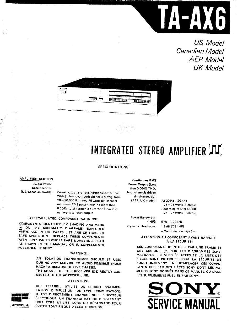
sony ta ax 6 service manual 2

Extracted text from sony ta ax 6 service manual 2 (Ocr-read)


Page 1

US Model
Canadian Model
AEP Model

UK Model

INTEGRATED STEREO AMPLIFIER-

SPECIFICATIONS

Continuous RMS
Power Ouput (Less
than 0.004% THD,
both channels driven
simultaneously)

AMPLIFIER SECTION

Audio Power

Spocificaxions
(US, Canadian model): Power outpui and mtal harmonic distortion:
With 8 Ohm ioadsl both channels driven, from
20- 20,000 Hz; rated 75 watts per channe!
minimum RMS power, with no more than
0.004% total harmonic distortion from 250
milliwatts to rated outpur.

SAFETV-RELATED COMPONENT WARNING Power BandWIdth

COMPONENTS IDENTIFIED BY SHADING AND MARK
A ON THE SCHEMATIC DIAGRAMS, EXPLODED
VIEWS AND IN THE PARTS LIST ARE CRITICAL TO
SAFE OPERATION. REPLACE THESE COMPONENTS
WITH SONY PARTS WHOSE PART NUMBERS APPEAR

(AEP, UK modal):

(IHF):
Dynamic Headroom:

At 20 H1 , 20 kHz
75 + 75 watts (8 ohms)
According to DIN 45500
75 + 75 watts (B ohmsI

5 Hz - 100 kHz
1.8 dB (78 IHFI
- Continued on page 2-

ATTENTION AU COMPOSANT AYANT RAPPORT

A LA SECURITE!

AS SHOWN IN THIS MANUAL OR IN SUPPLEMENTS
PUBLISHED BV SONY.

WARNING

AN ISOLATION TRANSFORMER SHOULD BE USED
DURING ANY SERVICE TO AVOID POSSIBLE SHOCK

HAZARD, BECAUSE OF LIVE CHASSIS.

THE CHASSIS OF THIS RECEIVER IS DIRECTLY CON-

NECTED TO THE AC POWER LINE
ATTENTIONI!

LES COMPOSANTS «ozmmss PAR UNE TRAME ET
UNE MAROUE A sun LES DIAGRAMMES scué
MATIQUES LES vuzs écLATéEs ET LA LISTE DES
PIECES sour cmnauss POUR LA sécumré DE
FONCTIONNEMENT. NE REMPLACER ces compo-
SANTS QUE PAR DES PIECES sonv DONT LES NU-
MéRos sour oomués DANS CE MANUEL ou DANS
LES SUPPLEMENTS PUBLIés PAR somv.

CET APPAREIL UTILISE UN CIRCUIT DALIMEN-
TATION D'IMPULSION (DE TYPE COMMUTATION)
IL EST DIRECTEMENT BRANCHE SUR LE SECTEUR

. SONY®

ELECTHIQUE UN TRANSFORMATEUR D' ISOLEMENT
DOIT ETRE UTILISE LOFIS DU DEPANNAGE POUR
EVITER TOUT RISQUE D' ELECTROCUTION.

MICHOFILM

SERVICE MANUAL

Page 2

TA-AX6

Harmonic distortion:

lntermodulation (IM)
Distortion (60 Hz:
7 kHz = 4 : 1):
Frequency Response:

Less than 0.004% at rated output

Less than 0.004% at rated output

PHONO: FllAA equalization curve 20.2dB
TUNER
AUX
TAPE 1, 2
Less than 23uV (8 ohms, network Al
100 (8 ohms, 1 kHz)

) 5H1-100kHz fgae

Residual Noise:
Damping Factor:

BASS
zBdB at 60 Hz (turnover freq. 500 Hz)
TREBLE

:BdB at 25 kHz (turnover freq. 5kHz)

Tone controls:

Bass Boost: +4dB at 50 Hz
Subsonic Filter: SdB/octave attenuation below 15 Hz
Mutiny: -2DdB
GENERAL
System: Preamplifier section: low-noise NF type

equalizer amp.,' NF tvoe tone control

lflplfli Power amplifier section pure-
Setting Maximum S/N complementary SEPP dc power amplifier
of the . _ . input (Weighting with all stages direct coupled
CARTRIDGE Sensmwty Impedance capability network, Power supply section: pulse power supply
selector (1 kHz) input level) circuitry
88 dB Power Requirements: 120V ac, 60 Hz (US. Canadian model)
MM MM 2.5mV 50m 160mV 86dB 220V ac, 50/60Hz (AEP model)
(A,2.5mVl 240Vac, 50H: IUK model)
FHONO. ................................. POW" C°"S"Pi°" 15° Wats (US "me
409 10011 EBdB 320 VA (Canadian model)
MC 0.17mV 8mV 75d3a 140 watts (AEP model)
39 309 (A, 0.17mVl 390 watts (UK model)
TUNER AC Outlets
AUX 93 dB lUS, Canadian model): Two switched (total 100 watts)
TAPE - ISOmV 50 kn - 10063 One unswitched (100 watts)
1' 2 (A' 150 "V) Dimensions: Approx. 430 x 105 x 350 mm Iw/h/d)
(17 x 41/. x137. inches)
78 IHF . . . .
Outputs: REC OUT 1' 2 including proiecting parts and controls
Voltage 150 mv Weight: Approx. 6.1 kg (13 lbs 70:) net
Impedance 1 k ohm Approx. 72 kg (15Ibs 14oz) in shipping car-
SPEAKER A, a ton
Accepts speakers of 8 to 16 ohms.
HEADPHON ES
Accepts low and high impedance head-
phones.

MAJOR DESIGN ELEMENTS AND CIRCUIT
FEATURES

Audio current drive amplifier

An unusual current transfer circuit design keeps
the preamplifier and power amplifier stages electrical-
1y separate, thus equalling the quality of separate
amplifiers.

Legato linear power amplifier stage

The operation of the power amplifier stage is
stable without any observable distortion up through
the higher frequencies. We call this power amplifier
legato linear", because its switching distortion is
very low and its output waveform smooth.

Shunt regulator for power supply section

The current-drive technique is also applied to the
power supply regulator. This amplifier employs a
constant current shunt regulator, instead of a con
ventional voltage regulator, to permit separate power-
ing of the preamplifier and power amplifier stages.

n... .o--.- .....--- .---a- -oo----------- --.------- .- .-,-.- .-.-.-.---.-.---.- .o.. .-a---.--- '---

MODEL IDENTIFICATION

- Specifica tian Label -

IVNTEGR TE

@

SERIAL NO.
MADE IN JAPAN

SONY® MODEL N0. TA-A X6
TEREO AMPLIFIER


AEP model: AC 220 V 50/60 Hz 140 W

UK model: AC 240 V 50/60 Hz 390 W

US model: AC 120 V 50 Hz 150 w
Canadian model: AC 120V 60 Hz 320 VA