Sony ta ax 3 service manual

This is the 16 pages manual for sony ta ax 3 service manual.
Read or download the pdf for free. If you want to contribute, please upload pdfs to audioservicemanuals.wetransfer.com.

Page: 1 / 16
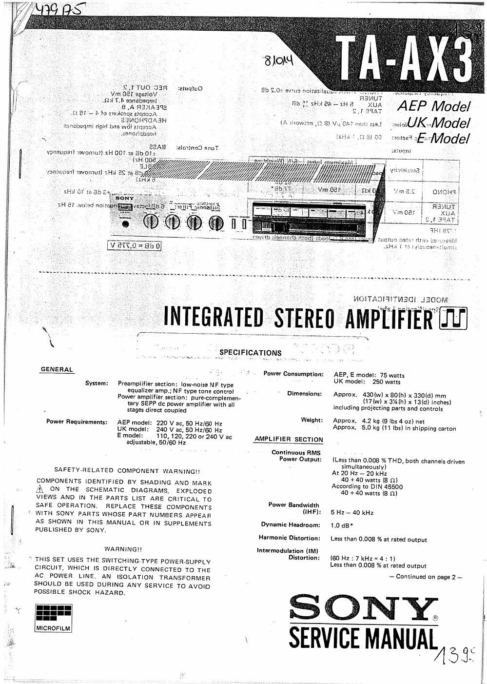
sony ta ax 3 service manual

Extracted text from sony ta ax 3 service manual (Ocr-read)


Page 1

. . Q QSrl magic-C)

Vm Gaiiaesfiov '

- :Sbl 7.3x sansoeoml - -
~ , '8 .A'RENABBS
at w h To 21% oz zlqeaaA :

, ; Mammals
0:3qu riggivi 13m; wo'l etqe~7A
,ea fibumi' ,


, EEAS :zloimoflonol

BIOM '

5b 320% 5w: _

§I~I>I as; sH

nwmq 1: SI kin-0.57 vVfil'I, aas.


\v-\ My. . gnaw: r. mqr .,

AEP Model
.UK .Moae/

SJEIIAT

Rm. ' .c': a) 0-: mm: 25;:M0de/

:zmqm

. we; may: iwommIVSHOG m 3130
, may} xsvommI XHJI

sit! Of


H a: waged Aoi:

FINIEGIlll

System: Preamplifier section: low~noise NF type
equalizer amp.; NF type tone control
Power amplifier section: pure-complemen-
tary SEPP dc power amplifier with all
stages direct coupled

Power Requirements: AEP model: 220 V ac, 50 Hz/BO Hz
UK model: 240 V ac, 50 Hz/eo Hz
Emodel: 110, 120, 220 or24OVac
adjustable, 50/60 Hz

SAFETY-RELATED COMPONENT WARNINGII

COMPONENTS IDENTIFIED BY SHADING AND MARK
[A ON THE SCHEMATIC DIAGRAMS, EXPLODED
VIEWS AND IN THE PARTS LIST ARE CRITICAL TO
SAFE OPERATION. REPLACE THESE COMPONENTS

I WITH SONY PARTS WHOSE PART NUMBERS APPEAR
AS SHOWN IN THIS MANUAL OR IN SUPPLEMENTS
PUBLISHED BY SONY.

WARNING

" THIS SET USES THE SWITCHING-TYPE POWER-SUPPLY
CIRCUIT, WHICH IS DIRECTLY CONNECTED TO THE
AC POWER LINE, AN ISOLATION TRANSFORMER
SHOULD BE USED DURING ANY SERVICE TO AVOID
POSSIBLE SHOCK HAZARD.

MICROFILM

GENERAL . :. ,

IEn§§iT7EREupT

. SPECIFICATIONS

Power Consumption:

Dimensions:

Weight:

AMPLIFIER SECTION

Continuous HMS
Power Output:

Power Bandwidth
(IH F):

Dynamic Headroom:
Harmonic Distortion:

Intermadulation llM)
Distortion:


MOITADHITWEQI .ISGOIVIILL

: ~-;.»...A\;. ..

IIIIIIPIfIF IER

AEP, E model: 75 watts
UK model: 250 watts

Approx. 430M) x BOIhI x 330ldl mm
(I7Iw) x 3%(hlx13(d)inches)
including projecting parts and controls

Approx. 4.2 kg (9 lbs 4 oz) net
Approx. 5.0 kg (11 lbs) in shipping carton

(Less than 0.008 % THD, both channels driven
simultaneously)

At 20 Hz - 20 kHz
40 + 40 watts (8 n)

According to DIN 45500
40 + 40 watts (8 m

5 Hz - 40 kHz
1.0 dB *
Less than 0.008 % at rated output

(60Hz:7kHz=4: 1)
Less than 0,008 % at rated output

-- Continued on page 2 -

SONY

SERVICE MANUAL 4 3 j.

Page 2

REC OUT 1, 2
Voltage 150 mV
Impedance 4.7 kn.

PHONO RIAA equalization curve 10.2 dB Outputs:

Fr uancyResponsa:
Sq TUNER

+0
Auge 1 25 Hz- 45 kHz " dB SPEAKER A, a
TA I Accepts speakers of 4 - 16 n.
L HEADPHONES
Residual Noise: Less than 140 uV (8 :2, network A) Accepts low and high Impedance
headphones.

Damping Factor: 50 I8 $7., 1 kHz)

Tone Controls: BASS

Inputs: 110 dB at 100 Hz (turnover irequency
Maximum Input S/N (WEIEMIHQ 500 HZ)
.. - '" - " N tw Mn m TFIEBLE
Sonsmwtv peda nee GETS-lg" 9 Logvsl) P 110 dB at 25 kHz (turnover frequency
82 dB 5 kHz)

PHONO 2.5 mV 50 kn 150 mV (Zr-12d: mVI Loudness (an. 30 d8): +10 dB at 100 Hz, +3 dB at 10 kHz
TUNER 5° kn ' 1g3 33* Subsonio Filter: 6 dB/octave attenuation below 15 Hz
TX§E1,2 150, (A,150 mVI
'78 IHF

Measured with rated output power into 8 r2 loads (both channels driven
simultaneously) at 1 kHz.

0 dB = 0,775 V

MODEL IDENTIFICATION
',_ Specification Label -

MODE L NO. TA-AX3

SONSQ

INTEGRATED STEREO AMPLIFIER

r J

SERIAL NO.
MADE IN JAPAN

AEP model: AC 220v ~ 50/60Hz 75w
UK model: AC 240v ~ 50/60H2 250w
E model: AC 110, 120, 220 or 240v, adjustable ~ 50/60Hz 75w

5

x. \\

TA X3

SERVICING NOTE

I. Pulse Power Supply Board Repairing

This set has a pulse power-supply circuit which
is quite different from a conventional power-
supply circuit. 'The pulse power-supply directly
rectifies and smooths the ac input power to
produce the higher dc voltages required in the
power-supply circuitr When servicing this set, note
the following.

a) To prevent unwanted radiation due to pulse
signals in the pulse power-supply circuit, the
pulse power-supply board is shielded by the
aluminum diecast box.

b) Take care that electrolytic capactitor which is
used after the rectification of ac power source
voltage is charged even if the POWER switch is
turned off. Be sure to use a resistor ofat least
several hundred ohms to discharge the capaci-
tor. Direct discharge byrsmcans of lead is
dangerous.

2. Inverter Circuit Transistor Replacement

When any of inverter transistors (Q903, 0904)
is broken, replace their transistors together. A pair
of transistors with the same rank'is'provided for
service field use. '

Ref. No.
(2903, Q904

Part No.
X-4869-209-1

Description

Transistor Assy, service

3. Inverter Circuit Transformer Replacement

The lead wire arrangement for each of T901
and T902 in the inverter circuit is shown in Fig. A.
As the'repair parts, T901 and T902 are formed

» by onlyiron core. Thus, if thecoil is defective,
_, arrange a new transformers as shown below. Note
that the lead lengths must be exact. Also winsthe
coil carefully.

T901 core (Part No. 1-543-098-00
7-543-100-00

' T902 core (Part No. 1-543400-00}

{WU turns

wire length: 80 mm (3% inches)

diameter : UL 1067 AWG28

two turns

wire length: 110 mm (43/,inches/
diameter : UL 1430 AWGZ4


six rum:
WireI length : 155 mm (61/; inches}
diameter : 0.4a)


BED

Enameled
Enameled

{ one turn


wire length: 45 mm (1% inches)
diameter : UL 1430AW622

wire length: 80 mm (3% inches}

two rams
diameter : UL 1051AWG28

PPS Board