Sony ta a 77 n service manual
This is the 23 pages manual for sony ta a 77 n service manual.
Read or download the pdf for free. If you want to contribute, please upload pdfs to audioservicemanuals.wetransfer.com.
Extracted text from sony ta a 77 n service manual (Ocr-read)
Page 1
SERVIc'E MANUAL
REVISED
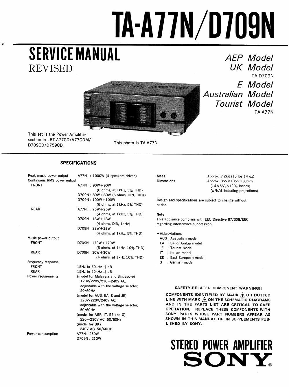
This set is the Power Amplifier
section in LBT-A77CD/A77CDM/
TA-ATIN/D'IIIBN
This photo is TA-A77N.
AEP Model
UK Model
TA-D709N
E Model
Australian Model
Tourist Model
TA-A77N
D709CD/D759CD.
SPECIFICATIONS
Peak music power output A77N : wow (4 speakers driven) Mass Approx 7.2kg (15 lbs 14 oz)
Continuous RMS power output Dimensions Approx. 355x135x330mm
FRONT A77N : 90W+90W (14X5IX127/s Inches)
(6 ohms, at 1kHz, 5% THD) (w/h/d, including projections)
D709N: 80W+80W (6 ohms, DIN, 1kHz)
D709N: 100W+100W Design and specifications are subject to change without
(6 ohms, at 1kHz, 5% THD) notice
REAR A77N : 25W+25W
(4 ohms, at 1kHz, 5% THD) Note
D709N: 18W+18W This appliance coniorms with EEC Directive 87/303/EEC
(4 ohms, DIN, 1kHz) regarding interference suppression.
D709N: 22W+22W
(4 ohms, at IKHL 5% THD) IAbbreviations
Music power output AUS: Australian model
FRONT D709N: 170W+170W EA : Saudi Ambia model
(6 ohms, at 1kHz, 10% THD) JE : Tourist model
REAR D709N: 30W+30W IT : Italian model
(4 ohms, at 1kHz 10% THD) EE : East European model
Frequency response G : German model
FRONT
REAR
Power requirements
Power consumption
15HZ to 50kHz :2 dB
15Hz to 50kHz :3 dB
(model for Malaysia and Singapore)
120V/220V/230-240V AC,
adjustable with the voltage selector.
50/60Hz
(model ior AUS, EA, E and JE)
120V/220V/240V AC,
adjustable with the voltage selector,
50/60Hz
(model for AEP, IT, EE and G)
220-230v Ac, 50/60Hz
(model tor UK)
240V AC, 50/60Hz
A77N: 250W
D709N: 210W
OPERATION.
SAFETYvRELATED COMPONENT WARNINGII
COMPONENTS IDENTIFIED BY MARK A OR DOTTED
LINE WITH MARK A ON THE SCHEMATIC DIAGRAMS
AND IN THE PARTS LIST ARE CRITICAL TO SAFE
REPLACE THESE COMPONENTS WITH
SONY PARTS WHOSE PART NUMBERS APPEAR AS
SHOWN IN THIS MANUAL OR IN SUPPLEMENTS PUB-
LISHED BY SONY.
STEREI] PDWER AMPLIFIER
ONY;
Page 2
MODEL IDENTIFICATION
-Speciiication Label-
AUS, EA, E. JE, MY, SP model: TA-A77N
AEPI IT. EE, 6, UK model : TA-D709N
SONY MODEL No. V/l/l/A
STEREO POWER AMPLIFIER
W A
SERIAL NO.
MADE IN JAPAN
AEP, IT, EE model : AC: 220V-230V~50/60Hz 210W
G model : SYSTEM LBT-D709
AC: 220V-230V~50/60Hz 210W
UK model : AC : 240V~50I60Hz
AUS, EA, E, JE model: AC: 120V/220V/240V~50/60Hz 250W
MY, SP model : AC: 120V/220V/230V-240V 50/60Hz 250W
NOTE FOR SERVICE
To input from the pin jack by using SEN / LBT service jig,
connect the SYSTEM CONTROL 3 (white) of TA-A77N/
D709N and the SYSTEM CONTROL 1 (blue) of the service
TABLE OF CONTENTS
Section Title nge
1. GENERAL
1-1. Parts Identification ............................... 2
2. SERVICE NOTES
2-1. Notes at Service and Inspection ................... 3
2-2. Removal of Joint ................................. 3
3. DIAGRAMS
3-1. Circuit Boards Location .......................... 4
3-2. Semiconductor Lead Layouts .....
3-3r Block Diagram ...................
3-4, Printed Wiring Boards (Type I )
3-5. Schematic Diagram (Type I) ..
3-6. Schematic Diagram (Type II) M
3-7. Printed Wiring Boards (Type II) . .
3-8. Printed Wiring Boards (Type III) . . .
3-9. Schematic Diagram (Type III) . . .
3-10. Schematic Diagram (Type IV) ..
3-11. Printed Wiring Boards (Type IV) .................. 37
4. EX PLODED VIEWS
jig with a 10pin or 11pin system cord. This allows pin input, 4-], Cabinet Section .................................. 41
4-2. Chassis Section .................................. 42
5. ELECTRICAL PARTS LIST ...................... 43
SECTION 1
G EN ERAL
1-1. PARTS IDENTIFICATION
This section is extracted from
instruction manual.
mPOWER switch (13)
@OPERATION indicator (18)
@RANGE switch (20)
ESPEAKERS SWliCh (20)
EPeak level meters (20) .
IEHEADPHONES jack (20)