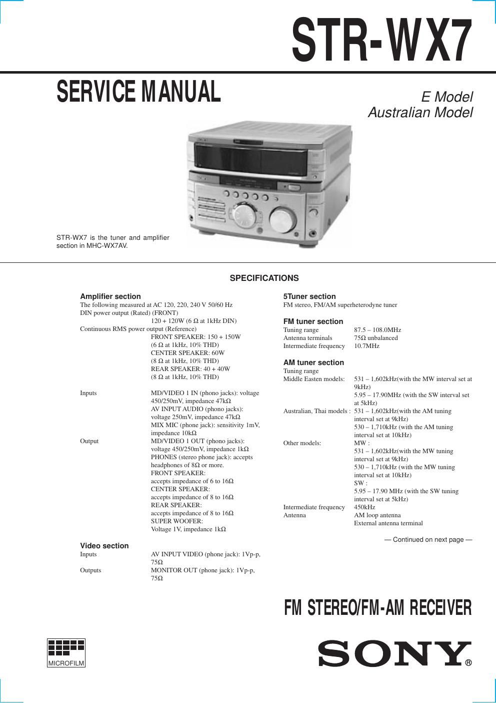
Sony str wx 7 service manual
This is the 44 pages manual for sony str wx 7 service manual.
Read or download the pdf for free. If you want to contribute, please upload pdfs to audioservicemanuals.wetransfer.com.
Extracted text from sony str wx 7 service manual (Ocr-read)
Page 1
2 TABLE OF CONTENTS 1. GENERAL ........................................................................... 3 2. DISASSEMBLY 2-1. Slideng Panel Assembly ááááááááááááááááááááááááááááááááááááááááááááááááááá\ áá 4 2-2. Level Slider ááááááááááááááááááááááááááááááááááááááááááááááááááá\ ááááááááááááááááááááá 4 3. SERVICE MODE .............................................................. 5 4. DIAGRAMS 4-1.Circuit Boards Locationáááááááááááááááááááááááááááááááááááááááááááááááááá 9 4-2.Block Diagrams ¥ Main Sectionááááááááááááááááááááááááááááááááááááááááááááááááááá\ ááááááááááááá 10 ¥ Power Sectionááááááááááááááááááááááááááááááááááááááááááááááááááá\ ááááááááááá 11 4-3. Printed Wiring Board Main Sectionááááááááááááááááááááááááá 12 4-4.Schematic Diagram Main (1/2) Sectionáááááááááááááááááááá 13 4-5. Schematic Diagram Main (2/2) Section ááááááááááááááááááááááááá 14 4-6. Schematic Diagram AV/Mic Section áááááááááááááááááááááááááááááá 15 4-7. Printed Wiring Board AV/Mic Section ááááááááááááááááááááááááááá 15 4-8. Schematic Diagram Power Amp Section ááááááááááááááááááááááá 16 4-9. Printed Wiring Board Power Amp Section ááááááááááááááááááááá 17 4-10. Schematic Diagram Display Section áááááááááááááááááááááááááááááá 18 4-11. Printed Wiring Board Display Section ááááááááááááááááááááááááááá 19 4-12. Schematic Diagram Sliding Panel Section ááááááááááááááááááááá 20 4-13. Printed Wiring Board Sliding Panel Section áááááááááááááááááá 21 4-14. Schematic Diagram Surround Section ááááááááááááááááááááááááááá 22 4-15. Printed Wiring Board Surround Section ááááááááááááááááááááááááá 23 4-16. Printed Wiring Board Trans Section ááááááááááááááááááááááááááááááá 24 4-17. Schematic Diagram Trans Section ááááááááááááááááááááááááááááááááá 25 4-18. IC Block Diagrams ááááááááááááááááááááááááááááááááááááááááááááááááááá\ áááááááá 26 4-19. IC Pin Function ááááááááááááááááááááááááááááááááááááááááááááááááááá\ ááááááááááááá 28 5. EXPLODED VIEWS 6-1. Case and Sliding Panel Section ........................................ 31 6-2. Front Panel Section .......................................................... 32 6-3. Slide Mechanism Section ................................................. 33 6-4. Circuit Boards and Back Panel Section ............................ 34 7. ELECTRICAL PARTS LIST ........................................ 35 LABEL MODEL NUMBER No. MODEL IDENTIFICATION Ñ BACK PANEL Ñ Saudi Arabia, Singapore, Malaysia, Australian model4-900-848-2¹ Thai model 4-900-848-3¹ MODEL PART No. SAFETY-RELATED COMPONENT WARNING!! COMPONENTS IDENTIFIED BY MARK ! OR DOTTED LINE WITH MARK ! ON THE SCHEMATIC DIAGRAMS AND IN THE PARTS LIST ARE CRITICAL TO SAFE OPERATION. REPLACE THESE COMPONENTS WITH SONY PARTS WHOSE PART NUMBERS APPEAR AS SHOWN IN THIS MANUAL OR IN SUPPLEMENTS PUBLISHED BY SONY. GeneralPower requirements Australian model: 240V AC, 50/60Hz Thailand model: 220V AC, 50/60Hz Other models: 120V or 220V or 230 Ð 240, 50/60Hz Adjustable with voltage selector Power consumption 340W Dimensions (w/h/d) Approx. 288 ´ 205 ´ 375mm Mass Approx. 8.8kg Design and specifications are subject to change without notice.
Page 2
3 Front Panel SECTION 1 GENERAL 1 2 3 4 5 6 7 8 9 !¼ !Á !ª !£ !¢ !° !¦ !¤ @° @¤ @¦ @¥ @» #£ #¢ #¼ !¥ !» @Á @£ @¢ @¼ #Á #ª @ª Rear Panel 2 4 53 1 6 7 1 MOVIE button 2 MUSIC button 3 GAME button 4 PLACE button 5 P FILE button 6 EFFECT ON/OFF button 7 OPEN/CLOSE button 8 TUNER BAND button 9 STEREO/MONO button !¼ TUNING MEMORY button !Á KARAOKE PON/MPX button !ª MIC LEVEL dial!£ MIX MIC jack !¢ GROOVE button !° VOLUME dial !¤ ) + button !¦ ENTER/NEXT button !¥ MULTI JOG STATION dial !» 0 Ð button @¼ NON-STOP button @Á EDIT button @ª FLASH button @£ PLAY MODE button @¢ REPEAT button@° PHONES jack @¤ LOOP button @¦ CLOCK/TIMER SET button @¥ TIMER SELECT button @» FUNCTION button #¼ PROLOGIC button #Á DSP button #ª DBFB button #£ DISPLAY/DEMO button #¢ I/u (POWER) button 1 SYSTEM CONTROL jack 2 ANTENNA terminal 3 CENTER SPEAKER terminal 4 REAR SPEAKER terminal 5 MONITOR OUT jack 6 FRONT SPEAKER terminal 7 MD/VIDEO 1 jack