Sony str w 55 service manual

This is the 27 pages manual for sony str w 55 service manual.
Read or download the pdf for free. If you want to contribute, please upload pdfs to audioservicemanuals.wetransfer.com.

Page: 1 / 27
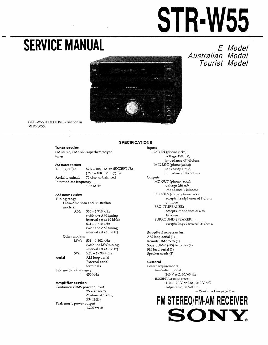
sony str w 55 service manual

Extracted text from sony str w 55 service manual (Ocr-read)


Page 1

SERVICE MANUAL

STR-WSS is RECEIVER section in
MHC-WSS.

STR-W55

E Model
Australian Mode/
Tourist Model

SPECIFICATIONS

Tuner section
FM stereo, FM/ AM superheterodyne
tuner

FM tuner section

Tuning range 87.5 - 103.0 MHz (EXCEPT JE)

(76.0 - 103.0 MHz)'(JE)
Aerial terminals 75 ohm unbalanced

Intermediate frequency
10.7 MHz
AM tuner section
Tuning range
Latin-American and Australian
models:
AM: 530 - 1,710 kHz
(with the AM tuning
interval set at 10 kHz)
531 - 1,710 kHz
(With the AM tuning
interVal set at 9 kl-Lz)
Other models:

MW: 531 --1,602 kHz
(with the MW tuning
interval set at 9 kHz)
SW: 595 -17.90 MHZ
Aerial M loop aerial
Bttemal aerial
terminals
Intermediate frequency
450 kHz

Amplifier section
Continuous RMS power output
75 + 75 watts
(6 ohms at I kHz,
5% THD)
Peak music power output
1,200 watts

Inputs
MD LN (phone jacks):
voltage 450 mV,
impedance 47 kilohms
MIX MIC (phone jacks):
sensitivity 1 mV,
impedance 10 kilohms
Outputs
MD OUT (phone jacks):
voltage 250 mV
impedance 1 kilohms
PHONES (stereo phone jack):
acceps headphones 058 ohms
01 more
FRONT SPEAKER:
accepts impedance of 6 to
16 ohms.
SURROUND SPEAKER:
accepts impedance at 16 ohms.

Supplied accessories

AM loop aerial (1)

Remote RM-SWSS (1)

Sony SUM-3 (NS) batteries (2.)
FM lead aerial (1)

Speaker cords (2)

General
Power requirements
Australian model:
240 V AC, 50/60 Hz
EXCEPT Australian model :
110-120 VorZZO-Z-io V AC
Adjustable, 50/60 Hz
- Continued on page 2 -

FM STEREO/FM-AM RECEIVER
S ONY;

Page 2

Power consumption
730 warts
Dimensions
Amplifier/Tuner section:
Approx 280 x 205 x 345 mm
(w/h/d)
Mass
Amplifier/Tuner section:
Approx, 6.4 kg

Design and specifications are subject to
dnange without notice.

Notes on chip component replacement

0 Never reuse a disconnected chip component
0 Notice that the minus side of a tantalum capacitor
may be damaged by heat.

SAFETY-RELATED COMPONENT WARNING-II

COMPONENTS IDENTIFIED BY MARK A OR DOT'I'ED
LINE WITH MARK A ON THE SCHEMATIC DIAGRAMS
AND IN THE PARTS LIST ARE CRITICAL TO SAFE
OPERATION. REPLACE THESE COMPONENTS WITH
SONY PARTS WHOSE PART NUMBERS APPEAR AS
SHOWN IN THIS MANUAL OR IN SUPPLEMENTS PUB-
LISHED BY SONY.

MODEL IDENTIFICATION
- BACK PANEL -


TABLE OF CONTENTS
Section Title Page
Specifications ............................................................... 1
1_ GENERAL ............................................................. 3
2. TEST MODE .......................................................... 4
3. ELECTRICAL ADJUSTMENTS ................................ 5
4. EXPLANATION OF IC TERMINALS ~~~~~~~~~~~~~~~~~~~~~~~~~~ 7
5. DIAGRAMS
5-1. Printed Wiring Boards ~ Main Section - ~
S»2l Schematic Diagram -- Main Section -
5-3, Schematic Diagram - Panel Section -
54 Printed Wiring Boards - Panel Section -
S-Sl Schematic Diagram - TCB Section -
5-6l Printed Wiring Boards - TCB Section -
6. EXPLODED VIEWS
6-1, Chassis Section
6-2, Front Panel Sectio 27
7_ ELECTRICAL PARTS LIST ................................... 28
Parts No. Model
4-978-033-1 [I E, Saudi Arabia, Argentine, Tourist
4-978-033~3 I] Australian
4-978»033-4 1:] Hong Kong
4-978-033-5 El Malaysia, Singapore, Mexican
4-980v482-0 I:I Thailand