Sony str h 2800 service manual

This is the 41 pages manual for sony str h 2800 service manual.
Read or download the pdf for free. If you want to contribute, please upload pdfs to audioservicemanuals.wetransfer.com.

Page: 1 / 41
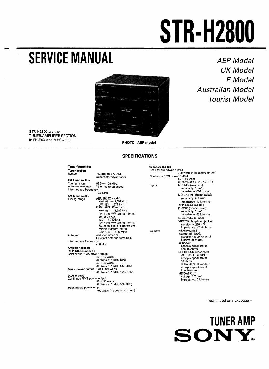
sony str h 2800 service manual

Extracted text from sony str h 2800 service manual (Ocr-read)


Page 2

General
Power requirements AEP, UK, EE model :
220 V - 230 V. 50/60 Hz
UK, AUS model :
240 V, 50H:
E, EA, JE model :
110-120V0r220-240VAC
adiustable, 50/60 Hz
Power consumption AEP, UK, EE model : 113 watts
E, EA, AUS, JE model :120 watts
Dimensions Approx. 255 x 175 x 270 mm (w/h/d)
(8 7/->< 6 'lmx 1O 3/: inches) incl. projecting
parts and controls
Mass Approx.4.6kg (10 lb 2 02)

Design and specifications subject to change
without notice.

Note

This appliance conforms with EEC Directive
87/308/EEC regarding interierence
suppression

EE : East European
EA : Saudi Arabia
AUS : Australian

JE : Tourist

SAFETY-RELATED COMPONENT WARNINGI!

COMPONENTS IDENTIFIED BY MARK A OR DOTTED LINE
WITH MARK A ON THE SCHEMATIC DIAGRAMS AND IN
THE PARTS LIST ARE CRITICAL TO SAFE OPERATION. REPLACE
THESE COMPONENTS WITH SONY PARTS WHOSE PART
NUMBERS APPEAR AS SHOWN IN THIS MANUAL OR IN
SUPPLEMENTS PUBLISHED BY SONY.

TABLE OF CONTENTS
Man He Rage
1. GENERAL
Parts Identification ................................................... 3
Clock Setting ............................................................ 4
2. ADJUSTMENTS
2-1. Test Mode ...................................................... 5
2-2. Tuner Section Adjustments ............................ 6
3. DIAGRAMS
3-1. Semiconductor Lead Layoutst....t.....,......t...,.. 8
3-2. Waveforms ..................................................... 9
3-3. Circuit Boards Location .................................. 10
3-4. Printed Wiring Boards (MAIN Section)
-AEP, UK, EE MODEL- ............. . 11
3-5. IO Block Diagram (MAIN Section) . 14
3-6. Schematic Diagram (MAIN Section)
- AEP, UK, EE MODEL-..
3-7t Schematic Diagram (MAIN Section)
- E, EA, AUS, JE MODEL -.. . 19
3-8 Printed Wiring Boards (MAIN Section)
- E, EA, AUS, JE MODEL - ........................... 23
3-9. Printed Wiring Boards (PANEL section) ........ 26
3-10. Schematic Diagram (PANEL Section) .. 29
3-11. Fluorescent Indicator Tube (FL301) . 33
3-12. IC Block Diagram (PANEL Section) ..... 33
3-13. Printed Wiring Boards (POWER AMP/POWER
SUPPLY Section) ........................................... 34
3-14. Schematic Diagram (POWER AMP/POWER
SUPPLY Section) ........................................... 37
3-15 IC Block Diagram (POWER AMP/POWER
SUPPLY Section) ........................................... 39
4. EXPLODED VIEWS
4-1. Front Panel Section ........................................ 40
4-2. Chassis Section............t. .. 41
5. ELECTRICAL PARTS LIST

SUPPLEMENT-1
SU PPLEMENT-2