Sony str dh 800 ver 1 0 2009 05 service manual

This is the 86 pages manual for sony str dh 800 ver 1 0 2009 05 service manual.
Read or download the pdf for free. If you want to contribute, please upload pdfs to audioservicemanuals.wetransfer.com.

Page: 1 / 86
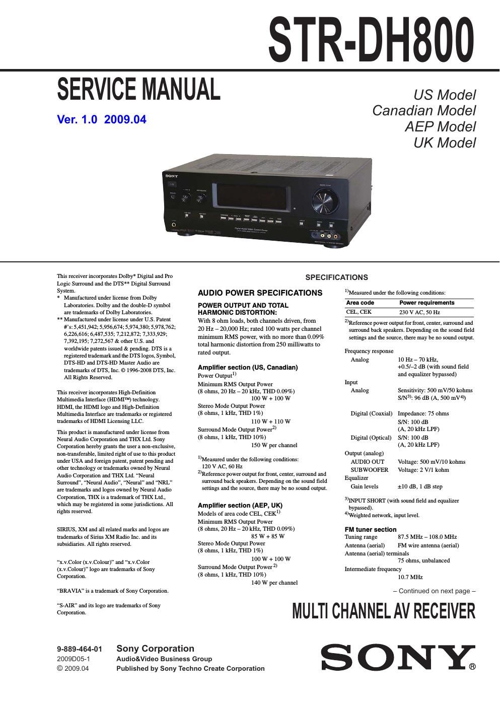
sony str dh 800 ver 1 0 2009 05 service manual

Extracted text from sony str dh 800 ver 1 0 2009 05 service manual (Ocr-read)


Page 1

STR-DH800

SERVICE MANUAL

Ver. 1.0 2009.04

US Model
Canadian Model
AEP Model

UK Model

This receiver incorporates Dolby" Digital and Pro
Logic Surround and the DTS** Digital Surround
System.

* Manufactured under license from Dolby
Laboratories. Dolby and the doublerD symbol
are trademarks of Dolby Laboratories.

** Manufactured under license under us. Patent
its: 5,451,942; 5,956,674; 5,974,330; 5,978,762;
6,226,616; 6,487,535; 7,212,372; 7,333,929;
7,392,195; 7,272,567 3; other US. and
worldwide patents issued 3r pending. DTS is a
registered trademark and the DTS logos, Symbol,
DTSVHD and DTSVHD Master Audio are
trademarks of DTS, Inc. e 199672008 DTS. Inc.
All Rights Reserved.

This receiver incorporates HighrDefinition
Multimedia Interface (HDMITM) technology.
HDMI, the HDMI logo and High~Definition
Multimedia Interface are trademarks or registered
trademarks of HDMI Licensing LLC.

This product is manufactured under license from
Neural Audio Corporation and THX Ltd. Sony
Corporation hereby grants the user a nonexclusive,
non»transferab1e. limited right of use to this product
under USA and foreign patent, patent pending and
other technology or trademarks owned by Neural
Audio Corporation and THX Ltd. Neural
Surround", Neural Audio", Neural" and NRL
are trademarks and logos owned by Neural Audio
Corporation, THX is a trademark of THX Ltd..
which may be registered in some jurisdictions. All
rights reserved.

SIRIUS, XM and all related marks and logos are
trademarks of Sirius XM Radio Inc. and its
subsidiaries. All lights reserved.

x.v.Color (x.v.Colour)" and x.v.Color
(x.v.Colour)" logo are trademarks of Sony
Corporation.

BRAVIA is a trademark of Sony Corporation.

SAIR and its logo are trademarks of Sony
Corporation.

9-889-464-01 Sony Corporation
2009D05-1 Audio&Video Business Group
© 2009.04

Published by Sony Techno Create Corporation

SPECIFICATIONS

AUDIO POWER SPECIFICATIONS

POWER OUTPUT AND TOTAL
HARMONIC DISTORTION:

With 8 ohm loads, both channels driven, from
20 Hz - 20,000 Hz; rated 100 watts per channel
minimum RMS power, with no more than 0.09%
total harmonic distortion from 250 milliwatts to
rated output.

Amplifier section (US, Canadian)
Power Output
Minimum RMS Output Power
(8 ohms, 20 Hz 7 20 kHz, THD 0.09%)
100 W + 100 W
Stereo Mode Output Power
(8 ohms, 1 kHz, THD 1%)
110 W + 110 W
Surround Mode Output Power
(8 ohms, 1 kHz, THD 10%)
150 W per channel

lMeasured under the following conditions:
120 v AC, 60 Hz

2Reference power output for front, center, surround and
surround back speakers. Depending on the sound field
settings and the source, there may be no sound output.

Amplifier section (AEP, UK)
Models of area code CEL, CEK
Minimum RMS Output Power
(8 ohms, 20 Hz 7 20 kHz, TI'H) 0.09%)
85 W + 85 W
Stereo Mode Output Power
(8 ohms, 1 kHz, THD 1%)
100 W + 100 W
Surround Mode Output Power 2)
(8 ohms, 1 kHz, THD 10%)
140 W per channel

Measured under the following conditions:

Area code

CEL, CEK 230 V AC, 50 Hz

2)Reference power output for front, center, surround and
surround back speakers. Depending on the sound field
settings and the source, there may be no sound output.

Frequency response

Analog 10 Hz 7 70 kHz,
+05er dB (with sound field
and equalizer bypassed)
Input
Analog Sensitivity: 500 mVl50 kohrns

SIN: 96 dB (A, 500 mV)

Digital (Coaxial) Impedance: 75 ohms

SIN: 100 dB
(A, 20 kHz LPF)
Digital (Optical) SIN: 100 dB
(A, 20 kHz LPF)
Output (analog)
AUDIO OUT Voltage: 500 mV/ 10 kohms

SUBWOOFER Voltage: 2 VII kohm
Equalizer

Gain levels :10 dB, 1 dB step

3)lNRU'l SHORT (with sound field and equalizer
bypassed).
Weighted network, input level.

FM tuner section
Tuning range 87.5 MHz 7 108.0 MHz
Antenna (aerial) FM wire antenna (aerial)

Antenna (aerial) terminals
75 ohms, unbalanced

Intermediate frequency
10.7 MHz

- Continued on next page -

MULTI CHANNEL AV RECEIVER

SONY;

Page 2

STR-DH800

AM tuner section

General

Tuning range Power requirements
Area code Tuning scale Area code Power requirements
lOkstwr Hump U,CA lZOVAC.60Hz
U, CA 530kHze 531 kHZr CEL, CEK 230V AC. 50/60Hz
1.7IOkHz 1,7lOkHz
CEL CEK 531 kHz Power output (DIGITAL MEDIA PORT)
' 1.602 kHz DC OUT: 5V, 0.7 A MAX

Antenna (aerial)
Intermediate frequency

Loop antenna

450 kHz
Video section
Inputs/Outputs
Video: 1 Vp-p, 75 ohms
COMPONENT VDEO:

Y: 1 Vp-p, 75 ohms

Power consumption

Area code Power consumption

U. CA, CEL. CEK 240 W

Power consumption (during standby mode)

0.9 W

(When CTRLJ-IDMI" in
HDM] menu is set to
CTRL OFF" and S-AIR
STBY" in SAAIR menu is set

Dimensions (width/heightldepth) (Approx)

17 x 61/4 x 12 3/4 inches
(430 x 157.5 x 322 mm)
including projecting parts
and controls

Mass (Approx.) 13 lb 5 oz (8.3 kg)
Supplied accessories

Operating instructions

Quick Setup Guide (1)

FM wire antenna (aerial) (1)

AM loop antenna (aerial) (1)

Remote commander (RM-AAPO43) (1)
R6 (size-AA) batteries (2)

Optimizer microphone (FEM-AC2) (1)

Design and specifications are subject to change
without notice.

Pa/Ca: 0.7 Vp-p, 75 ohms
Pit/CR: 0.7 Vp»p. 75 ohms
80 MHz HD Pass Through

About area codes

The area code of the receiver you purchased is
shown on the lower right portion of the rear panel
(see the illustration below).

@@

Q
=-r- 4.xxx-xxx-xx AA
=E'

as

Area code

Any differences in operation, according to the area
code, are clearly indicated in the text, for example,
Models of area code AA only".

SAFETY-RELATED COMPONENT WARNING!

COMPONENTS IDENTIFIED BY MARK A OR DOTTED LINE
WITH MARK A ON THE SCHEMATIC DIAGRAMS AND IN
THE PARTS LIST ARE CRITICAL TO SAFE OPERATION.
REPLACE THESE COMPONENTS WITH SONY PARTS
WHOSE PART NUMBERS APPEAR AS SHOWN IN THIS
MANUAL OR IN SUPPLEMENTS PUBLISHED BY SONY.

ATTENTION AU COMPO'SANT AYANT RAPPORT
A LA SECURITEI

LES COMPOSANTS IDENTIFIES PAR UNE MARQUE A SUR
LES DIAGRAMMES SCHEMATIQUES ET LA LISTE DES
PIECES SONT CRITIQUES POUR LA SECURITE DE FONC-
TIONNEMENT. NE REMPLACER CES COMPOSANTS QUE
PAR DES PIECES SONY DONT LES NUMEROS SONT DON-
NES DANS CE MANUEL 0U DANS LES SUPPLEMENTS
PUBLIES PAR SONY.

2

to STBY OFF)

NOTES ON CHIP COMPONENT REPLACEMENT

- Never reuse a disconnected chip component.

- Notice that the minus side ofa tantalum capacitor may be dam-
aged by heat.

SAFETY CHECK-OUT

After correcting the original service problem, perform the follow-
ing safety check before releasing the set to the customer:

Check the antenna terminals, metal trim, metallized knobs,
screws, and all other exposed metal parts for AC leakage.

Check leakage as described below.

LEAKAGE TEST

The AC leakage from any exposed metal part to earth ground and

from all exposed metal pans to any exposed metal part having a

return to chassis, must not exceed 0.5 mA (500 microamperes.).

Leakage current can be measured by any one of three methods.

1. A commercial leakage tester, such as the Simpson 229 or RCA
WT-54OA. Follow the manufacturers instructions to use these
instruments.

2. A battery»operated AC milliammeter. The Data Precision 245
digital multimeter is suitable for thisjob.

3. Measuring the voltage drop across a resistor by means of a
VOM or battery-operated AC voltmeter. The limit indication
is 0.75 V, so analog meters must have an accurate low-voltage
scale. The Simpson 250 and Sanwa SI-I-63Trd are examples
ofa passive VOM that is suitable. Nearly all battery operated
digital multimeters that have a 2 V AC range are suitable. (See
Fig. A)

To Exposed Metal
Parts on Set

A C
/ voltmeter
(0. 75 V)

g 1.5 k0

Q15pF

_T_ Earth Ground
Fig. A. Using an AC voltmeter to checkAC leakage.