Sony str de 515 service manual

This is the 16 pages manual for sony str de 515 service manual.
Read or download the pdf for free. If you want to contribute, please upload pdfs to audioservicemanuals.wetransfer.com.

Page: 1 / 16
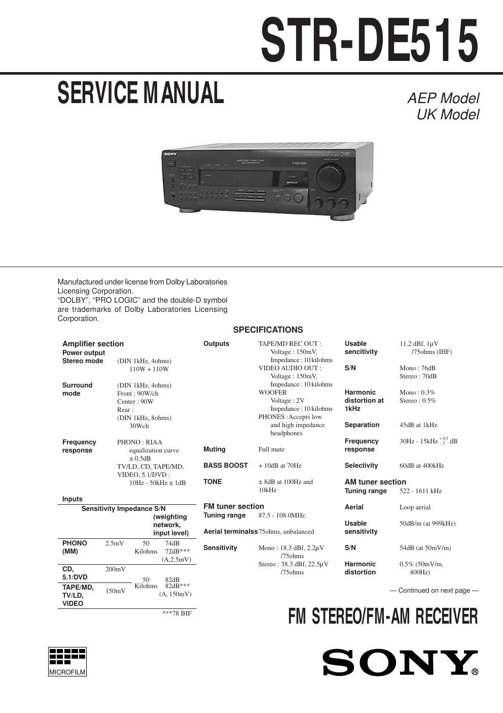
sony str de 515 service manual

Extracted text from sony str de 515 service manual (Ocr-read)


Page 1

Ñ 2 Ñ TABLE OF CONTENTS Specifications ááááááááááááááááááááááááááááááááááááááááááááááááááá\ áááááááááááááááááááááááááááá 1 1. GENERAL Location and Function of controls áááááááááááááááááááááááááááááááááááááááááááááááá 3 2. EXPLANATION OF IC TERMINALSááááááááááááááááááá 5 3. DIAGRAMS 3-1. Circuit Boards Location ááááááááááááááááááááááááááááááááááááááááááááááááááá\ áá 7 3-2. Printed Wiring Boards (Main Section) ááááááááááááááááááááááááááááááá 8 3-3. Schematic Diagram (Main Section) ááááááááááááááááááááááááááááááááá 13 3-4. Schematic Diagram (Display Section) ááááááááááááááááááááááááááááá 18 3-5. Printed Wiring Boards (Display Section) ááááááááááááááááááááááááá 21 4. EXPLODED VIEWS 4-1. Front Panel Section ááááááááááááááááááááááááááááááááááááááááááááááááááá\ ááááááá 25 4-2. Chassis Section ááááááááááááááááááááááááááááááááááááááááááááááááááá\ áááááááááááááá 26 5. ELECTRICAL PARTS LISTáááááááááááááááááááááááááááááááá 27 Selectivity35dB General SystemTuner section : PLL quartz-locked digital synthesizer system Preamplifier section : Low-noise NF type equalizer Power amplifier section : Pure-complimentary SEPP Power230V AC, 50/60Hz requirements Power230W consumption AC outletsSwitched 100W Dimensions430 ´ 145 ´ 295mm Mass (Approx.)7.2kg SuppliedFM wire aerial (1) accessoriesAM loop aerial (1) Remote controller (remote) (1) Size AA (R6) batteries (2) Scart adaptor (1) Design and specifications are subject to change without notice. SAFETY-RELATED COMPONENT WARNING!! COMPONENTS IDENTIFIED BY MARK ! OR DOTTED LINE WITH MARK ! ON THE SCHEMATIC DIAGRAMS AND IN THE PARTS LIST ARE CRITICAL TO SAFE OPERATION. REPLACE THESE COMPONENTS WITH SONY PARTS WHOSE PART NUMBERS APPEAR AS SHOWN IN THIS MANUAL OR IN SUPPLEMENTS PUBLISHED BY SONY.

Page 2

Pin No.123456789101112131415161718192021222324252627282930313233343536373839 40 I/OOOOOOOOÑIIIOOIOIIIIÑOOOOIIIIÑÑÑÑÑIOOOOO O Description Fluorescent indicator tube drive. Power supply (+5V).System clock.System data.PLL data input from TU001.Chip enable output.Chip enablr output.Input for model slect.Standby relay ON/OFF control.Protector detect input.System reset terminal.Auto stop detect input.Stereo detect input.Ground.Speaker relay drive.Surround Relay.Power relay drive.Not used.A/D signal input terminal.A/D3 key input terminal.A/D2 key input terminal.A/D1 key input terminal.Power supply (+5V).Reference voltage (+5V).Ground.Not used (Open).Ground.System clock (4.19MHz).System clock (4.19MHz).Mute drive output for mPD2581V (IC701).Plologic LED drive.CINEMA STUDIO LED drive.Hall LED drive. Tuner mute drive output. Pin NameDIG7DIG6DIG5DIG4DIG3DIG2DIG1+5VS. CLKS. DATAPLL. DATAS. CE (LC7288)S. CE (LV100)REARRYBRIDGE CABLEPROTECTRESETAUTO-STOPSTEREO-INAVssSP-RYSURR-RYPOWER-RYNot usedSIGNALA/D3A/D2A/D1AVDDAV. R E FGNDNCVssX1X2IC. MUTEPROLOGICCSTUDIOHALL T. MUTE SECTION 2 EXPLANATION OF IC TERMINALS Pin No.414243444546474849505152535455565758596061626364656667686970717273747576777879 80 I/OOOOIIIIÑIIOÑOOOIIIIIOOOOOOOOOOÑOOOOOOOO O Description Volume up.Volume down.Standby LED drive.System power ON/OFF.RDS data input terminal.RDS clock input terminal.Stop signal input from NJM2103D (IC950).Ground.Sircs signal input.Power switch input terminal.5.1ch input LED.Power supply (+5V).Bass boost LED drive.Line mute drive.Surround Lch mute.Input for model select.Key in 4.Key in 3.Key in 2.Key in 1.Surround Rch mute.Key out 15.Key out 14.Key out 13.Key out 12.Key out 11.Key out 10.Key out 9.Key out 8.Key out 7.Connect to Ð24V.Key out 6.Key out 5.Key out 4.Key out 3.Key out 2.Key out 1. Fluorescent indicator tube drive. Pin NameVOLUME UPVOLUME DOWNSTANDBYSYS. POWERRDS. DATA. INRDS. CLK. INSTOPVssSIRCSPOWER SW5.1ch LED+5VBASS BOOSTFUNC. MUTESL MUTEVERSIONK14K13K12K11SR MUTES15S14S13S12S11S10S9S8S7VLOADS6S5S4S3S2S1DIG10DIG9 DIG8 SECTION 3 DIAGRAMS ü ï ï ï ý ï ï ï þ Fluorescent indicator tube drive. 3-1. CIRCUIT BOARDS LOCATION Ñ 3 ÑÑ 4 ÑÑ 5 ÑÑ 6 ÑÑ 7 Ñ IC201 : mPD78044FGF-064-3B9 SP-SW boardPRIMARY boardSECONDARY board STBY board MAIN board VIDEO board SWITCH board VOLUME board VR TONE board KEY board DISPLAY board SECTION 1 GENERAL LOCATION AND FUNCTION OF CONTROLS ü ï ï ý ï ï þFluorescent indicator tube drive. 123 5 4 6 7 8 9 !¼ !Á !ª !£ !¢ !° !¤ !¦ !¥ !» @¼ @Á @ª @£ @¢ @° @¤ 1 23 4 5 6 7 8 9 !¼ !Á !ª !¢ !° !£ 1 POWER switch 2 CENTER LEVEL +, Ð buttons 3 REAR LEVEL +, Ð buttons 4 STANDBY indicator 5 FUNCTION indicators 6 5.1 INPUT indicator 7 MASTER VOLUME control 8 BALANCE control 9 TREBLE control !¼ BASS control !Á BASS BOOST button/indicator !ª SURROUND ON/OFF button !£ MODE button!¢ EFFECT/DELAY TIME, SET UP, 5.1/DVD INPUT buttons !° TAPE/MD button !¤ PHONO button !¦ TV/LD button !¥ TUNER button !» VIDEO button @¼ CD button @Á DIRECT button @ª SHIFT button @£ Numeric buttons @¢ Tuner control buttons @° PHONES jack @¤ SPEAKERS (A/B) buttons 1 5.1 INPUT (FRONT/REAR/CENTER/WOOFER) 2 WOOFER 3 WIRELESS REAR SPEAKER 4 AC OUTLET 5 AC power cord 6 FRONT SPEAKERS (A/B) 7 SURROUND SPEAKERS (CENTER) 8 SURROUND SPEAKERS (REAR)9 VIDEO !¼ TV/LD !Á TAPE/MD !ª CD !£ PHONO !¢ ANTENNA (FM/AM) !° SIGNAL GND