Sony str de 135 rec service manual

This is the 30 pages manual for sony str de 135 rec service manual.
Read or download the pdf for free. If you want to contribute, please upload pdfs to audioservicemanuals.wetransfer.com.

Page: 1 / 30
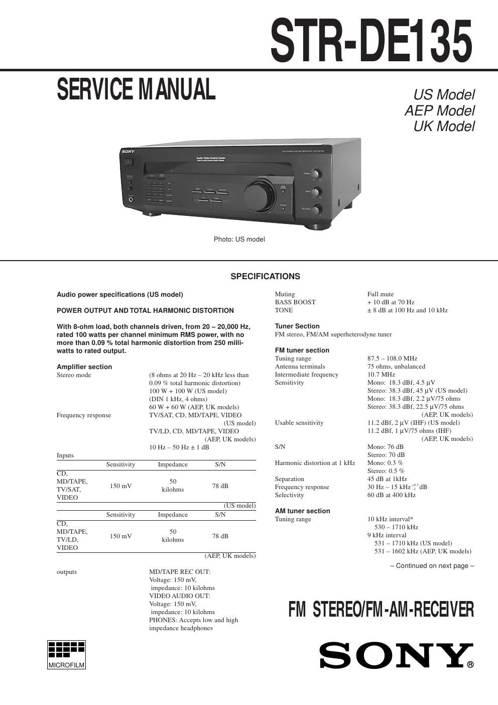
sony str de 135 rec service manual

Extracted text from sony str de 135 rec service manual (Ocr-read)


Page 1

Ð 2 Ð TABLE OF CONTENTS 1. SERVICING NOTES ............................................... 3 2. GENERAL ................................................................... 4 3. DISASSEMBLY ......................................................... 5 4. TEST MODE ............................................................... 7 5. DIAGRAMS 5-1. Note for Printed Wiring Boards and Schematic Diagrams ....................................................... 9 5-2. Printed Wiring Board Ð MAIN Board Ð ........................ 11 5-3. Schematic Diagram Ð MAIN Board (1/2) Ð .................. 13 5-4. Printed Wiring Boards Ð DISPLAY Board/KEY Board/VOLUME Board/ TONE Board/POWER SWITCH Board Ð ................... 15 5-5. Schematic Diagram Ð PANEL Section Ð ......................................................... 19 5-6. Printed Wiring Boards Ð PANEL Section Ð ......................................................... 23 5-7. Schematic Diagram Ð MAIN Board (2/2)/SPK SWITCH Board/ SECONDARY Board/PRIMARY Board/ STANDBY TRANS Board Ð ....................................... 25 5-8. IC Pin Function Description ........................................... 26 6. EXPLODED VIEWS ................................................ 28 7. ELECTRICAL PARTS LIST ............................... 31 SAFETY-RELATED COMPONENT WARNING!! COMPONENTS IDENTIFIED BY MARK ! OR DOTTED LINE WITH MARK ! ON THE SCHEMATIC DIAGRAMS AND IN THE PARTS LIST ARE CRITICAL TO SAFE OPERATION. REPLACE THESE COMPONENTS WITH SONY PARTS WHOSE PART NUMBERS APPEAR AS SHOWN IN THIS MANUAL OR IN SUPPLEMENTS PUB- LISHED BY SONY. Antenna Loop antenna Intermediate frequency 450 kHz Usable sensitivity 50 dB/m (at 1,000 kHz) S/N 54 dB (at 50 mV/m) Harmonic distortion 0.5 % (50 mV/m, 400Hz) Selectivity At 10 kHz: 40 dB At 9 kHz: 35 dB (US model) 35 dB (AEP, UK models) * You can change the AM tuning interval between 9 kHz and 10kHz. After tuning in any AM station, turn off the receiver. Hold down the PRESET TUNING + button and press the 1/u (power) button. All pre- set stations will be erased when you change the interval. To reset the interval, repeat the procedure. (US model) General System Tuner section: PLL quartz-locked digital synthesizer system Preamplifier section: Low-noise NF type equalizer Power amplifier section: Pure-complementary SEPP Power requirements 120 V AC, 60 Hz (US model) 230 V AC, 50/60 Hz (AEP, UK models) Power consumption 155 W (US model) 135 W (AEP, UK models) AC outlets 1 switched, total 120 W/1A Max (US, UK models) switch 100 W max (AEP model) Dimensions 430 ´ 144 ´ 306 mm (17 ´ 5 6/8 ´ 12 4/8 inches) Mass (Approx.) 8.1 kg (17 lb 13 oz) (US model) 6.7 kg (AEP, UK models) Supplied accessories FM wire antenna (1) AM loop antenna (1) Remote commander (remote) (1) Size AA (R6) batteries (2) Specifications indicated are measured at 230 V AC, 50Hz. (AEP, UK models) Design and specifications are subject to change without notice.

Page 2

Ð 3 Ð SECTION 1 SERVICING NOTES MODEL IDENTIFICATION Ð Rear view Ð 12345 PART No. MODEL PART No. US model 4-216-802-0¹ AEP model 4-216-802-1¹ UK model 4-216-802-2¹ SAFETY CHECK-OUT After correcting the original service problem, perform the follow- ing safety check before releasing the set to the customer: Check the antenna terminals, metal trim, ÒmetallizedÓ knobs, screws, and all other exposed metal parts for AC leakage. Check leakage as described below. LEAKAGE TEST The AC leakage from any exposed metal part to earth ground and from all exposed metal parts to any exposed metal part having a return to chassis, must not exceed 0.5 mA (500 microampers.). Leakage current can be measured by any one of three methods. 1. A commercial leakage tester, such as the Simpson 229 or RCA WT-540A. Follow the manufacturersÕ instructions to use these instruments. 2. A battery-operated AC milliammeter. The Data Precision 245 digital multimeter is suitable for this job. 3. Measuring the voltage drop across a resistor by means of a VOM or battery-operated AC voltmeter. The ÒlimitÓ indica- tion is 0.75 V, so analog meters must have an accurate low- voltage scale. The Simpson 250 and Sanwa SH-63Trd are ex- amples of a passive VOM that is suitable. Nearly all battery operated digital multimeters that have a 2 V AC range are suit- able. (See Fig. A) Fig. A. Using an AC voltmeter to check AC leakage. 1.5 k W 0.15 µF AC voltmeter (0.75 V) To Exposed Metal Parts on Set Earth Ground