Sony st v 502 service manual
This is the 14 pages manual for sony st v 502 service manual.
Read or download the pdf for free. If you want to contribute, please upload pdfs to audioservicemanuals.wetransfer.com.
Extracted text from sony st v 502 service manual (Ocr-read)
Page 1
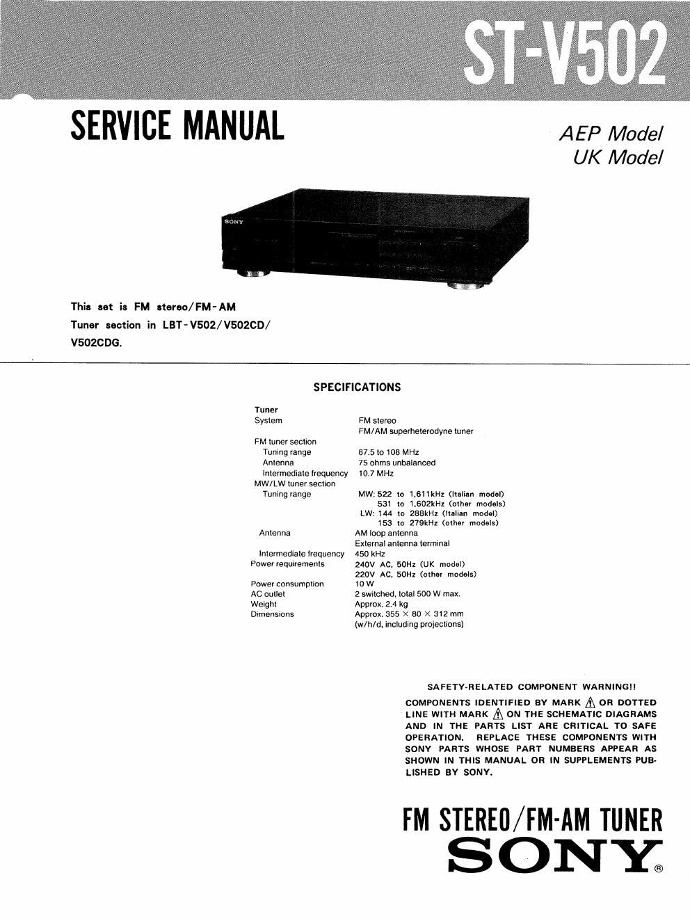
SERVICE MANUAL
A E P Model
UK Model
This set i: FM stereo/FM-AM
Tuner section in LBT-V502/V502CD/
VSOZCDG.
SPECIFICATIONS
Tuner
System
FM tuner section
Tuning range
Antenna
Intermediate frequency
MW/LW tuner section
Tuning range
Antenna
Intermediate frequency
Power requirements
Power consumption
AC outlet
Weight
Dimensions
FM stereo
F M/ AM superheterodyne tuner
37.5 to 108 MHz
75 ohms unbalanced
10.7 MHZ
MW: 522 to 1.611kHz (Italian model)
531 to 1.602kHz (other models)
LW: 144 to 288kHz (Italian model)
153 to 279kHz (other models)
AM loop antenna
External antenna terminal
450 kHz
240V AC. 50Hz (UK model)
220V AC. 50Hz (other models)
I0 W
2 switched. total 500 W max.
Approx. 2.4 kg
Approx. 355 X 80 X 312 mm
(w/h/d, including projections)
SAFETY-RELATED COMPONENT WARNINGII
COMPONENTS IDENTIFIED BV MARK & 0R DOTTED
LINE WITH MARK & ON THE SCHEMATIC DIAGRAMS
AND IN THE PARTS LlST ARE CRITICAL TO SAFE
OPERATION. REPLACE THESE COMPONENTS WITH
SONY PARTS WHOSE PART NUMBERS APPEAR AS
SHOWN IN THIS MANUAL OR IN SUPPLEMENTS PUB-
LISHED BY SONY.
FM STEREO/FM-AM TUNER
SONY;
Page 2
ST- V502
SECTION 1
SERVICING NOTES
Note on Ceramic Filter (CF1,2,3) A Replacement.
This set employs three ceramic filters (CF1,2,3) A which
should have the same color marking to identify their center
frequency, Therefore FM IF offset adjustment by >I= D609, *
D610 is necessary to match the center frequency of the
ceramic filters used with FM intermediate frequency.
color marking
(CFI,2,3) A
Q: Mounted
X : not Mounted
Ceramic filter Mount , F M
Intermediate
Color Center frev frequency
mark quency (MHz) * D609 * D610 (MHz)
White 10750 O x 10.750
Red 10.700 X X 10.700
Black 10.650 X 0 10650
FM intermediate frequency is determined by the three
types as shown above, Ceramic filters of same center fre-
quency,i.e., of same color coding should be used for CFl, CF2,
and CF 3.
When replacing the ceramic filters. perform the FM Di»
scriminator Adjustment.
A: AEP, UK Model: CFl, 2
WG, IT Model: CFl, 2, 3
MODEL IDENTIFICATION
- Specification Label --
SONYo MODEL N0. ST-vsoz
FM STEREO/FM - AM TIMER TUNER
SERIAL N04
MADE IN JAPAN
AEP. West Germany,
Italian Model: AC: 220V ~ 50/60 Hz
UK Model : AC : 240V ~ 50/60 Hz
LOCATION OF CONTROLS
Display window
Buttons for setting the clock and timer
SYSTEM powea switch
Remote sensor
E] SLEEP button
IE} FREQUENCWTIME button
Buttons tor storing slalion frequencies
TUNING buttons
[El BAND selector
MEMORY SCAN button
AUTO tuning button