Sony st s 5 service manual

This is the 38 pages manual for sony st s 5 service manual.
Read or download the pdf for free. If you want to contribute, please upload pdfs to audioservicemanuals.wetransfer.com.

Page: 1 / 38
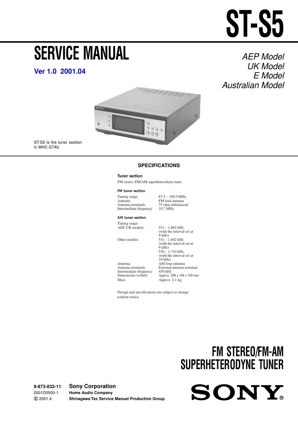
sony st s 5 service manual

Extracted text from sony st s 5 service manual (Ocr-read)


Page 1

2 ST-S5 TABLE OF CONTENTS 1. SERVICING NOTES ................................................ 3 2. GENERAL Location of Controls ....................................................... 4 Setting the Time .............................................................. 5 3. DISASSEMBLY 3-1. Disassembly Flow ........................................................... 6 3-2. Cover ............................................................................... 7 3-3. Front Panel Section ......................................................... 7 3-4. PANEL Board, SIRCS Board ......................................... 8 3-5. Tuner pack (FM/AM) ...................................................... 8 3-6. MAIN Board ................................................................... 9 3-7. DSP Board ....................................................................... 9 4. TEST MODE .............................................................. 10 5. DIAGRAMS 5-1. Note for Printed Wiring Boards and Schematic Diagrams ....................................................... 11 5-2. Schematic Diagram – MAIN Board (1/2) –.................. 12 5-3. Schematic Diagram – MAIN Board (2/2) –.................. 13 5-4. Printed Wiring Board – MAIN Board –........................ 14 5-5. Printed Wiring Board – DSP Board –............................ 15 5-6. Schematic Diagram – DSP Board (1/2) –..................... 16 5-7. Schematic Diagram – DSP Board (2/2) –..................... 17 5-8. Printed Wiring Boards – PANEL Section –.................. 18 5-9. Schematic Diagram – PANEL Section –....................... 19 5-10. IC Pin Function Description ........................................... 21 6. EXPLODED VIEWS 6-1. Cover, Front Panel Section ............................................. 28 6-2. Chassis Section ............................................................... 29 7. ELECTRICAL PARTS LIST ............................... 30Notes on chip component replacement -Never reuse a disconnected chip component. -Notice that the minus side of a tantalum capacitor may be dam- aged by heat. SAFETY-RELATED COMPONENT WARNING!! COMPONENTS IDENTIFIED BY MARK 0 OR DOTTED LINE WITH MARK 0 ON THE SCHEMATIC DIAGRAMS AND IN THE PARTS LIST ARE CRITICAL TO SAFE OPERATION. REPLACE THESE COMPONENTS WITH SONY PARTS WHOSE PART NUMBERS APPEAR AS SHOWN IN THIS MANUAL OR IN SUPPLEMENTS PUB- LISHED BY SONY.

Page 2

3 ST-S5 SECTION 1 SERVICING NOTES - MODEL IDENTIFICATION – Rear Panel – This set is a component of the MHC-S7AV. The MHC-S7AV system configuration is as shown below, and therefore it does not operate normally unless all four components are connected. In performing the repair, connect all components with the system cables. Note: The precaution to the users is described on the label stuck on the back panel (CD player) and in the troubleshooting section in the Operation Manual. System Configuration: POWER SUPPLYAC IN TA SYSTEM & CD µcon ST CDP TC µcon TC DISPLAY MODEL PART No. AEP and UK models 4-232-327-0 [] Australian model 4-232-327-1 [] Mexican model 4-232-327-4 [] Korean model 4-232-327-9 [] PART No.