Sony ss tsl 10 service manual
This is the 62 pages manual for sony ss tsl 10 service manual.
Read or download the pdf for free. If you want to contribute, please upload pdfs to audioservicemanuals.wetransfer.com.
Extracted text from sony ss tsl 10 service manual (Ocr-read)
Page 1
SA-WSLF10/
SS-CTL1 0/T SL1 U/T SL11
SERVICE MANUAL
Ver. 1.0 2005.03
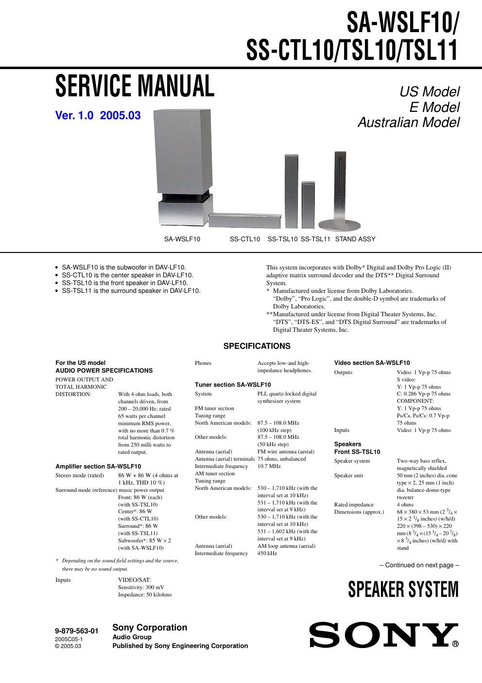
SA-WSLF10
US Model
E Model
Australian Model
SS-CTLIO SS-TSL10 SS-TSL11 STAND ASSY
SA-WSLF10 is the subwoofer in DAV-LF10.
SS-CTL10 is the center speaker in DAV-LF10.
SS-TSL10 is the front speaker in DAV-LF10.
SS-TSL11 is the surround speaker in DAV-LF10.
This system incorporates with Dolby* Digital and Dolby Pro Logic (II)
adaptive matrix surround decoder and the DTS** Digital Surround
System.
* Manufactured under license from Dolby Laboratories.
Dolby", Pro Logic, and the double-D symbol are trademarks of
Dolby Laboratories.
Manufactured under license from Digital Theater Systems, Inc.
DTS, DTS-ES, and DTS Digital Surround are trademarks of
Digital Theater Systems, Inc.
SPECIFICATIONS
For the US model Phones
Accepts lowennd highe Video section SA-WSLF10
AUDIO POWER SPECIFICATIONS impedance headphones. Ompms Video: 1 WW 75 ohms
POWER OUTPUT AND S video:
TOTAL HARMONIC Tuner 59cm)" SA'WSI-FW Y: 1 Vprp 75 ohms
DISTORTION: With 4 ohm loads, both System PLL quarIZrlocked digital c: 0.286 Vpp 75 ohms
channels driven, from synthesizer system COMPONENT:
200 , 20.000 Hz; rated FM tuner section Y: 1 Vprp 75 ohms
65 watts per channel Tuning range Pia/ct, Pit/CR: 0.7 Vprp
minimum RMS power, North American models: 87.5 , 108.0 MHz 75 ohms
with no more than 0.7 % (100 kHz step) Inputs Video: 1 Vprp 75 ohms
total harmonic distortion Other models: 87.5 e l08.0 MHz
from 250 milli watts to (50 kHz step) Speakers
rated output. Antenna (aerial) FM wire antenna (aerial) From ss.'rs|_1o
Antenna (aerial) terminals 75 ohms. unbalanced Speaker System Twoway bass reflex
Amplifier section SA-WSLF10 Intermediate frequency 10.7 MHz magnetically shielded
Stcrco modc (rated) 85 w + 86 w (4 ohms at AM tuner Swim Speaker unit 50 mm (2 inches) dia. cone
Tuning range
North American models:
1 kHz. THD 10 %)
Surround mode (reference) music power output
Front: 86 w (each)
(with SSVTSLIO)
Center*: 86 w
(with SSeCTLIO)
Surround": 86 w
(with SS TSLl 1)
Subwoofer": 85 w x 2
(with SAVWSLFIO)
Other models:
Antenna (aerial)
Intermediate frequency
* Depending on the xnmtdfieltl sent-upl- and rim tonne,
tlmc may be 7L0 mum] output
Inputs VIDEO/SAT:
Sensitivity: 300th
Impedance: 50 kilohms
9_879_553_01 Sony Corporation
2005C05r1 AUdiO Group
©2005.03 Published by Sony Engineering Corporation
type x 2, 25 mm (1 inch)
dia. balanceedomeetype
tweeter
530 , 1710 kHz (with the
interval set at 10 kHz)
53171710 kHz (with the
interval set at 9 kHz)
530 71710 kHz (with the
interval set at 10 kHz)
531 , [(602 kHz (with the
interval set at 9 kHz)
AM loop antenna (aerial)
450 kHz
4 ohms
68 X 380 x 53 mm (2 3/4 x
15 x 2 UK inches) (w/h/d)
220 x1398 , 530) x 220
mm183/4X(153l47207lg)
X 8 3/4 inches) (wlh/d) with
stand
Rated impedance
Dimensions (approx. )
- Continued on next page -
SPEAKER SYSTEM
S O NY®
Page 2
SA-WSLF10/SS-CTL10/TSL10/TSL11
Mass (approx) 1.3 kg (2 lb 14 oz)
2.7 kg (6 lb) with stand
Canter SS-CTL10
Speaker system Tworway bass rellex.
magnetically shielded
Speaker unit 50 mm (2 inches) dia. cone
type x2. 25 mm (1 inch)
dia. balallcerdomertype
tweeter
Rated impedance 4 ohms
Dimensions (approx) 68 x 380 X 53 mm (2 V4 X
15 X 2 3. inches) (w/h/d)
Mass (approx) 1.3 kg (2 lb 14 oz)
Surround SS-TSL11
Speaker system Tworway bass rellex.
magnetically shielded
Speaker unit 50 mm (2 inches) dia. cone
type x2. 25 mm (1 inch)
dia. balallcerdomertype
tweeter
Rated impedance 4 ohms
Dimensions (approx) 68 x 240 X 53 mm (2 3/4 X
9 l/Z X 2 UK inches) (w/li/d)
Mass (approx ) 1.0 kg (2 lb 4 oz)
Subwoofer SA-WSLF10
Speaker System Bass retlex
Speaker unit 180 mm (7 1/8 inches) dia.
cone 1) pa
Rated impedance 4 ohms x 2
Dimensions (approx) 241 x 606 X 241 mm
(91/2 x 23 7/X X 9 1/2
inches) (w/h/d)
Mass (approx) 14 kg (3011; 14 oz)
Power requirements
North American models: 120 V AC, or) 1-12
Taiwan model: 120 V AC. 50/60 Hz
Other models: 2207240 v AC. 50/60 Hz
Power consumption 120 w
0.3 w (at the RowerSaving
mode)
Design and specifications are subject [0 change
without notice.
Notes on chip component replacement
0 Never reuse a disconnected chip component.
' Notice that the minus side of a tantalum capacitor may be
damaged by heat.
SAFETY CHECK-OUT
After correcting the original service problem, perform the following
safety check before releasing the set to the customer:
Check the antenna terminals, metal trim, metallized knobs, screws,
and all other exposed metal parts for AC leakage.
Check leakage as described below.
LEAKAGE TEST
The AC leakage from any exposed metal part to earth ground and
from all exposed metal parts to any exposed metal part having a
return to chassis, must not exceed 0.5 mA (500 microamperes.).
Leakage current can be measured by any one of three methods.
1. A commercial leakage tester, such as the Simpson 229 or RCA
WT-540A. Follow the manufacturers instructions to use these
instruments.
2. A batteryeoperated AC milliammeter. The Data Precision 245
digital multimeter is suitable for this job.
3. Measuring the voltage drop across a resistor by means of a
VOM or battery-operated AC voltmeter. The limit" indication
is 0.75 V, so analog meters must have an accurate low-voltage
scale. The Simpson 250 and Sanwa SH-63Trd are examples
ofa passive VOM that is suitable. Nearly all battery operated
digital multimeters that have a 2 V AC range are suitable. (See
Fig. A)
To Exposed Metal
Parts on Set
AC
0.15uF g 1.5 kt} / voltmeter
(o. 75 V)
_ Earth Ground
Fig. A. Using an Ac voltmeter to check AC leakage.
SAFETY-RELATED COMPONENT WARNING !!
COMPONENTS IDENTIFIED BY MARK A OR DOTTED LINE
WITH MARK A ON THE SCHEMATIC DIAGRAMS AND IN
THE PARTS LIST ARE CRITICAL TO SAFE OPERATION.
REPLACE THESE COMPONENTS WITH SONY PARTS WHOSE
PART NUMBERS APPEAR AS SHOWN IN THIS MANUAL OR
IN SUPPLEMENTS PUBLISHED BY SONY.