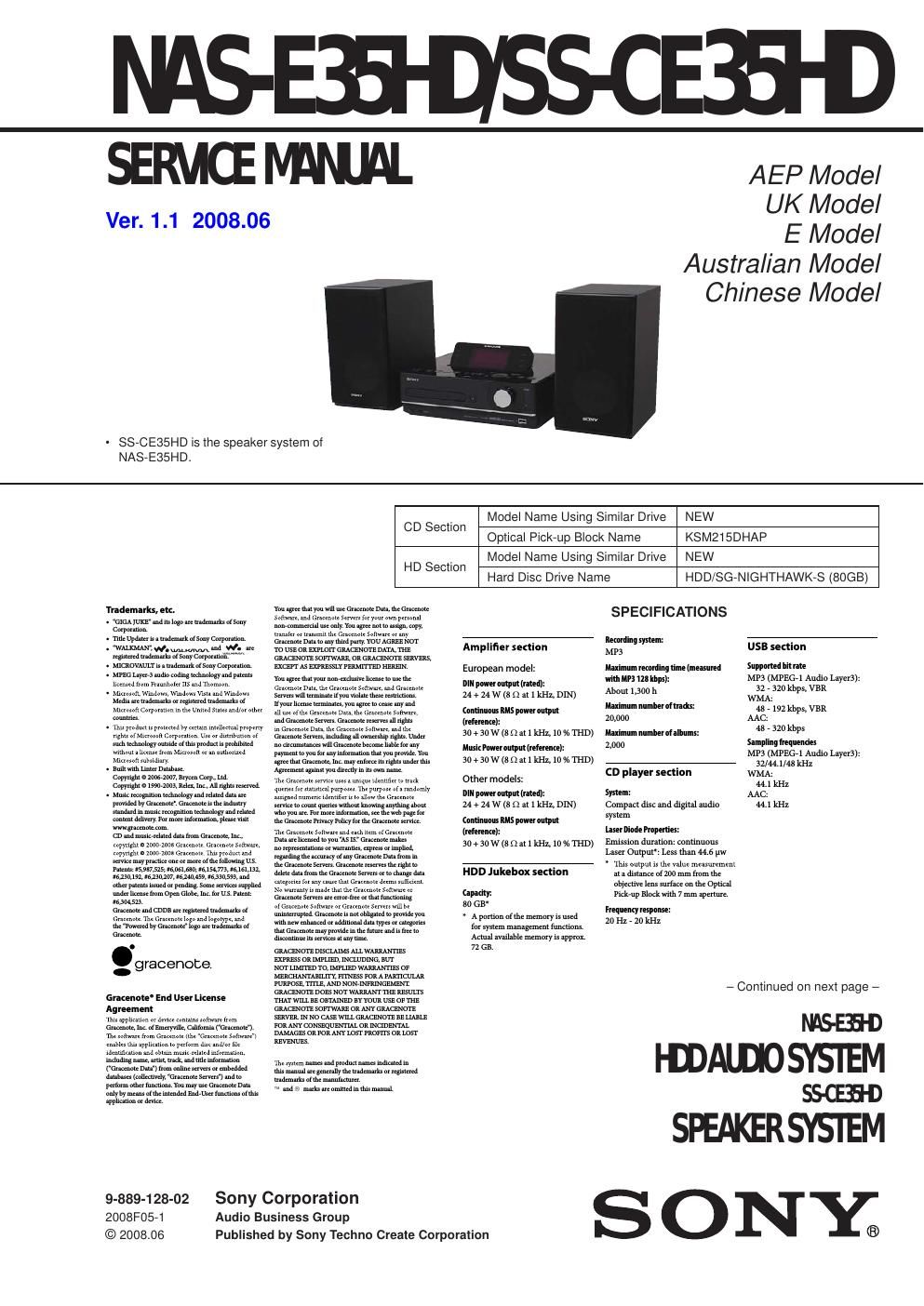
Sony ss ce 35 hd service manual
This is the 100 pages manual for sony ss ce 35 hd service manual.
Read or download the pdf for free. If you want to contribute, please upload pdfs to audioservicemanuals.wetransfer.com.
Extracted text from sony ss ce 35 hd service manual (Ocr-read)
Page 1
NAS-E35HD/SS-CE35HD 2 NOTES ON CHIP COMPONENT REPLACEMENT - Never reuse a disconnected chip component. - Notice that the minus side of a tantalum capacitor may be dam-aged by heat. FLEXIBLE CIRCUIT BOARD REPAIRING - Keep the temperature of soldering iron around 270 °C during repairing. - Do not touch the soldering iron on the same conductor of the circuit board (within 3 times). - Be careful not to apply force on the conductor when soldering or unsoldering. SAFETY-RELATED COMPONET WARNING! COMPONENTS IDENTIFIED BY MARK 0 OR DOTTED LINE WITH MARK 0 ON THE SCHEMATIC DIAGRAMS AND IN THE PARTS LIST ARE CRITICAL TO SAFE OPERATION. REPLACE THESE COMPONENTS WITH SONY PARTS WHOSE PART NUMBERS APPEAR AS SHOWN IN THIS MANUAL OR IN SUPPLEMENTS PUBLISHED BY SONY. DAB frequency table (Band-III): Frequency Label174.928 MHz 5A 176.640 MHz 5B 178.352 MHz 5C 180.064 MHz 5D 181.936 MHz 6A 183.648 MHz 6B 185.360 MHz 6C 187.072 MHz 6D 188.928 MHz 7A 190.640 MHz 7B 192.352 MHz 7C 194.064 MHz 7D 195.936 MHz 8A 197.648 MHz 8B 199.360 MHz 8C 201.072 MHz 8D 202.928 MHz 9A 204.640 MHz 9B 206.352 MHz 9C 208.064 MHz 9D 209.936 MHz 10A 211.648 MHz 10B 213.360 MHz 10C 215.072 MHz 10D 216.928 MHz 11A 218.640 MHz 11B 220.352 MHz 11C 222.064 MHz 11D 223.936 MHz 12A 225.648 MHz 12B 227.360 MHz 12C 229.072 MHz 12D 230.784 MHz 13A 232.496 MHz 13B 234.208 MHz 13C 235.776 MHz 13D 237.488 MHz 13E 239.200 MHz 13F Inputs/Outputs AUDIO IN (stereo mini jack): Voltage 0.8 V, impedance 22 k (USB) port: USB type A, Full speed USB DMPORT: For connecting a DIGITAL MEDIA PORT adapter (headphones) jack (stereo mini jack): Accepts headphones of 8 Ωor more Asian model: AUDIO OUT (phono jacks): Voltage 0.5 V, impedance 1 k Speaker Latin American model: Speaker system: Speaker units: Woofer: 120 mm, cone type Nominal impedance: 8 Ω Dimensions (w/h/d) Approx. 140 × 284 × 240 mm Mass Approx. 2.7 kg net per speaker Other models: Speaker system: Speaker units: Woofer: 120 mm, cone type Tweeter: 40 mm, cone type Nominal impedance: 8 Ω Dimensions (w/h/d) Approx. 140 × 250 × 210 mm Mass Approx. 2.0 kg net per speaker General Power requirements: Mexican model: 120 V AC, 60 Hz Taiwan model: 120 V AC, 50/60 Hz Brazilian model: 127 or 220 V AC, 50/60 Hz (adjustable with voltage selector) Latin American model (except for the Mexican, Argentine and Brazilian models): 110 - 120 or 220 - 240 V AC, 50/60 Hz (adjustable with voltage selector) Other models: 220 - 240 V AC, 50/60 Hz Power consumption: 45 W Dimensions (w/h/d): UK model: Approx. 285 × 130 × 319 mm incl. projecting parts and controls Other models: Approx. 285 × 130 × 312 mm incl. projecting parts and controls Mass: Approx. 4.0 kg Operating temperature: +5 °C (+41 °F) to +35 °C (+95 °−F) Operating humidity: 25 % to 80 % Supplied accessories: subjecttochangewithoutnotice. (SS-CE35HD) AM loop antenna (1) FM lead antenna (1) DAB lead antenna (1) (for the UK model only) Speaker cords (2) Speaker pads (8) (for the Latin American model only) Remote control (1) R6 (size AA) batteries (2) DIGITAL MEDIA PORT adapter (TDM-iP10 (M) ) (1) (for the European model only) iPod Dock Adapters (1 set) (for the European model only) Operating Instructions FM tuner section Tuner: FM stereo, FM superheterodyne tuner Circuit system: PLL digital frequency synthesizer quarts lock system Frequency range: 87.5 - 108.0 MHz (50kHz step) Brazilian model: Other models: 87.5 - 108.0 MHz (100kHz step) Antenna: FM lead antenna Antenna terminals: 75 Ω unbalanced Intermediate frequency: 10.7 MHz AM tuner section Tuner: AM superheterodyne tuner Circuit system: PLL digital frequency synthesizer quarts lock system Frequency range: European model: 531 - 1,602 kHz (with the interval set at 9 kHz) LatinAmericanmodel: 530 - 1,710 kHz (with the interval set at 10 kHz) 531 - 1,710 kHz (with the interval set at 9 kHz) Oceanian model 531 - 1,710 kHz (with the interval set at 9 kHz) 530 - 1,710 kHz (with the interval set at 10 kHz) Other models: 531 - 1,602 kHz (with the interval set at 9 kHz) 530 - 1,610 kHz (with the interval set at 10 kHz) Antenna: AM loop antenna Antenna terminals: External antenna terminal Intermediate frequency: 450 kHz DAB tuner section (UK model only) Tuner: DABstereotuner Antenna: DAB lead antenna Frequency range: Band-III: 174.928 (5A) – 239.200 (13F) MHz CAUTION Use of controls or adjustments or performance of procedures other than those speci fi ed herein may result in hazardous radia- tion exposure. This appliance is classifi ed as a CLASS 1 LASER product. This marking is located on the rear or bottom exterior. Ve r. 1 . 1
Page 2
NAS-E35HD/SS-CE35HD 3 1. SERVICING NOTES ............................................. 4 2. GENERAL .................................................................. 6 3. DISASSEMBLY 3-1. Disassembly Flow ........................................................... 8 3-2. Panel (Side L/R) .............................................................. 9 3-3. Top Panel Block .............................................................. 9 3-4. HP JACK Board, KEY (FRONT) Board, Panel (Front) Assy .......................................................... 10 3-5. POWER Board ................................................................ 10 3-6. FL Block ........................................................................\ . 11 3-7. DISPLAY Board ............................................................. 11 3-8. DAB Board, DMP Board, Tuner (FM/AM) .................... 12 3-9. MAIN Board ................................................................... 13 3-10. CD Mechanism Block ..................................................... 13 3-11. USB MICOM Board ....................................................... 14 3-12. HDD Assy ....................................................................... 14 3-13. Base Unit ........................................................................\ . 15 3-14. Belt ........................................................................\ .......... 15 3-15. OP Base Assy (KSM215DHAP) ..................................... 16 4. TEST MODE ............................................................ 17 5. ELECTRICAL CHECKS ...................................... 20 6. DIAGRAMS 6-1. Block Diagram - CD SERVO, PANEL Section -............ 21 6-2. Block Diagram - USB, HDD Section - ........................... 22 6-3. Block Diagram - MAIN Section - ................................... 23 6-4. Block Diagram - POWER SUPPLY Section - ................ 24 6-5. Printed Wiring Board - CD Board - ................................ 26 6-6. Schematic Diagram - CD Board - ................................... 27 6-7. Schematic Diagram - USB MICOM Board (1/4) - ......... 28 6-8. Schematic Diagram - USB MICOM Board (2/4) - ......... 29 6-9. Schematic Diagram - USB MICOM Board (3/4) - ......... 30 6-10. Schematic Diagram - USB MICOM Board (4/4) - ......... 31 6-11. Printed Wiring Board - USB MICOM Board - ............... 32 6-12. Schematic Diagram - MAIN Board (1/3) - ..................... 33 6-13. Schematic Diagram - MAIN Board (2/3) - ..................... 34 6-14. Schematic Diagram - MAIN Board (3/3) - ..................... 35 6-15. Printed Wiring Board - MAIN Board (Component Side) - ................................ 36 6-16. Printed Wiring Board - MAIN Board (Conductor Side) - .................................. 37 6-17. Printed Wiring Boards - DAB, DMP Section - ............... 38 6-18. Schematic Diagram - DAB, DMP Section - ................... 39 6-19. Printed Wiring Board - D-AMP Board - ......................... 40 6-20. Schematic Diagram - D-AMP Board - ............................ 41 6-21. Printed Wiring Boards - SPEAKER Section - ................ 42 6-22. Schematic Diagram - SPEAKER Section - .................... 42 6-23. Printed Wiring Board - DISPLAY Board (Component Side) - .......................... 44 6-24. Printed Wiring Board - DISPLAY Board (Conductor Side) - ............................ 45 6-25. Schematic Diagram - DISPLAY Board (1/2) - ............... 46 6-26. Schematic Diagram - DISPLAY Board (2/2) - ............... 47 6-27. Printed Wiring Boards - PANEL Section - ..................... 48 6-28. Schematic Diagram - PANEL Section - .......................... 49 6-29. Printed Wiring Board - D/D CON Board - ..................... 50 6-30. Schematic Diagram - D/D CON Board - ........................ 51 6-31. Printed Wiring Board - POWER Board - ........................ 52 6-32. Schematic Diagram - POWER Board - .......................... 53 6-33. Printed Wiring Board - MOTOR Board - ....................... 54 6-34. Schematic Diagram - MOTOR Board - .......................... 54 TABLE OF CONTENTS 7. EXPLODED VIEWS 7-1. Panel Section ................................................................... 73 7-2. Top Panel Section ........................................................... 74 7-3. Main Section ................................................................... 75 7-4. HDD Section ................................................................... 76 7-5. Chassis Section ............................................................... 77 7-6. Loading Mechanism Section .......................................... 78 7-7. Base Unit Section ............................................................ 79 7-8. Speaker Section (SS-CE35HD) ...................................... 80 8. ELECTRICAL PARTS LIST .............................. 81 Accessories are given in the last of the electrical parts list.