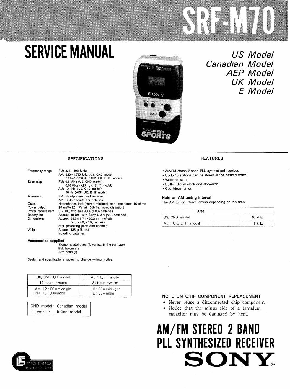
Sony srf m 70 service manual
This is the 10 pages manual for sony srf m 70 service manual.
Read or download the pdf for free. If you want to contribute, please upload pdfs to audioservicemanuals.wetransfer.com.
Extracted text from sony srf m 70 service manual (Ocr-read)
Page 1
SERVICE MANUAL
pom»
W or;
US Model
Canadian Model
AEP Model
UK Model
E Model
Frequency range FM:
AM:
Scan step FM:
AM:
Antennas FM:
AM:
Output
Power output
SPECIFICATIONS
875-108 MHZ
530-1110 kHz (us. CND model)
531-1.602kHz (AEP. UK. E, lT model)
0.1 MHz (US. CND model)
0.05Ml-lz (AEP. UK. E. IT model)
10 kHz (us. CND model)
9kHz (AEP. UK, E, IT model)
Headphones cord antenna
Buiit~in lerrite bar antenna
Headphones lack (stereo minijack) load impedance 16 ohms
20 mW+20 mW (at 10% harmonic distortion)
Power requirement 3 V DC. two size AAA (H03) batteries
Battery lite
Dimensions
Approx. 18 hrs. with Sony UMA (NU) batteries
Approx. 665 X111! x 303 mm (wlhld)
(2% x 45/a x W. inches)
excl. projecting pans and controls
Weight
Approx. 135 g (5 oz.)
including batteries.
Aocessorles supplled
Stereo headphones (l. vertical-in-theear type)
Belt holder (1)
Arm band (I)
Design and specifications subject to change Without notice.
US. CND. UK model
AEP. E. IT model
12-hours system
24hour system
AM 12: OO=midnight
PM 12: 002noon
0 : 00=rnidnight
12 : 00= noon
IT model :
CND model: Canadian model
Italian model
FEATURES
- AMIFM stereo 2-band PLL synthesized receiver:
- Up to 10 stations can be stored in the desired order.
- Water-resistant.
- Built»in digital clock and stopwatch.
- Countdown timer.
Note on AM tuning intenml
The AM tuning interval diflers depending on the area.
Area
US. CND model
10 kHz
AEP. UK. E. |T model
9 kHz
NOTE ON CHIP COMPONENT REPLACEMENT
0 Never reuse a disconnected chip component.
0 Notice that the minus side of a tantalum
capacitor may be damaged by heat.
AM/FM STEREO 2 BAND
PLL SYNTHESIZEI] RECEIVER
SONE
Page 2
SECTION 1
ELECTRICAL ADJUSTMENTS
AM Section
AM RF signal
generator
Put the lead-wire
/|/ antenna close to
O the set.
30% amplitude
modulation by
400Hz signal
Output level : as low as possible
FM RF signal
generator
60% 0'01 TP
|-> FM ANT
input terminal
:22.5kHz trequency deviation
by 40on signal
Output level :as low as possible
VTVM
m
%% i L
set
'-o
PHONES jack
' Repeat the procedures in each adjustment several times.
and the tracking adjustments should be finally the
trimmer capacitors.
FM FREQUENCY COVERAGE ADJUSTMENT
Adjustment Frequency Reading on Digital
Part. Display voltmeter
L4 108MHz 10V
Note 1 Not use the FM signal generator in this adjustment.
FM TRACKING ADJUSTMENT
Adjust for a maximum reading on VTVM.
CT2 1.3-1, 1.3-2
108MHz 37.5MH2
AM FREQUENCY COVERAGE ADJUSTMENT
Adjustment Frequency Reading on Digital
Part Display voltmeter
L5 1,710kHZ (1,602kHZ) 8V (7.3V)
Note : Not use the AM rf signal generator in this adjustment.
AM TRACKING ADJUSTMENT
Adjust for a maximum reading on VTVM.
CTl L2
1,490kHz (1,395kHz) 580kHz (SZIkHz)
AM iF ADJUSTMENT
Adjust for a maximum reading on VTVMt
T1 450kHz
( ) : AEP, UK. E, [T model
FM VCO Adjustment
Procedure :
FM RF signal Tl
generator FM ANT
input terminal
E w
Carrier frequency : 108MHz
Modulation 2 no modulation
Output level 2 lmV (6MB)
Connect frequency counter to it as shown below.
Tune the set to 108 MHZ.
Adjust RVl for 76 kHzilOO l-lz reading on the
frequency counter.
93.